The application of distributed optical strain sensing to measure the strain distribution of ground support members
Abstract
A distributed optical strain-sensing technique is presented as a solution for measuring the strain distribution along ground support members used in tunnelling and mining works. The technique employs a Rayleigh optical frequency domain reflectometry technology, which measures strain at a spatial resolution of 0.65 mm along the length of a standard optical fiber. A rationale for selecting this technology as a potential monitoring technique for ground support elements over alternative commercially available technologies is discussed. The development of a technique to couple optical fiber sensors with rock bolt, umbrella arch, and cable bolt support members is also demonstrated. A robust laboratory investigation of such optically instrumented support members demonstrated the capability of the technique to capture the expected in situ support behaviour in the form of coaxial, lateral, and shear loading arrangements as would be anticipated in the field. Moreover, the micro-scale data obtained by this optical sensing technique are shown to provide unprecedented insight into the local/micro-scale geomechanistic complexities associated with the bearing capacity of ground support members, especially when compared with data obtained by discrete strain-sensing technologies.
Introduction
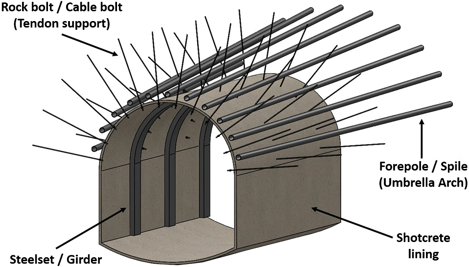
A rising demand for subterranean transportation and resource management has led to the development of many more underground projects that are constructed at larger scales, over greater distances, at increased depths, and within proximity to sensitive urban environments (i.e., reduced tolerances with respect to adjacent infrastructure). The result in any given project is a wide variety of ground mass and in situ stress conditions that will often require some form of ground support or reinforcement. Ground support is a general term used to describe the procedures and materials used to improve the stability and to maintain the load-bearing capacity of ground near the excavation boundaries (e.g., Brady and Brown 1993). This term can be subdivided into multiple distinct categories (e.g., Windsor and Thompson 1993) depending on conditions such as the manner by which it strengthens the ground mass (i.e., internally, within the ground mass, or externally, at the excavation boundary), whether it applies an active load to the ground (i.e., active or passive), and its expected serviceability life. An example of an underground support system that consists of multiple support components is shown in Fig. 1.
Fig. 1.
During the construction stage of a project, the support system acts as the first line of defense for workers and equipment at the working face, and it is pivotal in controlling excavation-induced displacements to meet project-related limitations and regulations. An incorrect evaluation of the support system can result in catastrophic consequences to both life and property when underestimated, and it can also result in excessive costs to the project if an overly conservative design is selected and implemented (Marr 2001). An observational construction approach (e.g., Austrian Society for Geomechanics 2010) provides a design rationale whereby the support system is systematically and continuously updated according to current excavation conditions rather than designing for the worst-case scenario. This permits the installation of a less costly and time-intensive support system (Kontogianni and Stiros 2002); however, this also necessitates a comprehensive monitoring program to verify or falsify the assumptions made during the support design (Schubert 2008). A strong understanding of the geomechanical behaviour and response of the support system and its constituent support elements is of critical significance to this design procedure (in addition to an understanding of the rock mass properties and expected behaviour). In terms of monitoring, this has conventionally been approached from an external perspective whereby measurements of displacement at the excavation periphery (e.g., surveying and other remote sensing techniques) and (or) ground displacements surrounding the support elements (e.g., multi-point borehole extensometers) have been used to infer support behaviour rather than direct coupling with the support system itself. Possible explanations for this approach are the difficulties of operationally instrumenting ground support elements (i.e., so as not to impede construction operations) as well as the relatively coarse resolution an array of discrete strain–load instrumentation techniques (e.g., electrical-resistance strain gauges) can provide along an individual support element or support system. Consequently, the current practice of ground support sensing results in a partial understanding (and capturing) of related mechanisms and parameters that can be used in both the assessment and the predictive modelling of ground support, especially at the micro-scale level.
Within this context, a consideration of innovative sensing techniques such as fiber optic sensing (FOS) provides an opportunity to fill in the gaps of knowledge with regards to the geomechanical response of support elements in isolation and as part of a multi-component support system. This research investigates several FOS techniques and provides a rationale for selecting a particular distributed optical strain-sensing (DOS) technique, with a view of measuring and capturing the performance of support elements and an unprecedented spatial resolution. The development of an instrumentation technique to couple the chosen DOS technology with rock bolt, umbrella arch (UA), and cable bolt support elements is discussed and demonstrated through a series of laboratory experiments.
Monitoring ground support: Fiber optic strain sensing
The geomechanistic response of a support system will depend on many of the physical and interface parameters associated with the host ground medium, the installation technique (e.g., the use of encapsulating grout, active loading), and the support member material/typology (e.g., Haas 1976; Azuar 1977; Spang and Egger 1990; Kilic et al. 2003). A sensing technique that is not inherent to the support system will require significant assumptions regarding the transfer of ground mass displacements to the support member/system; however, there are numerous challenges to an intrinsic sensing solution, for example:
i.
The chosen sensing technology must be coupled with a support tendon.
ii.
The chosen sensor(s) and corresponding lead wires must be protected from environmental conditions.
iii.
The application of the sensor(s) must not interfere with or alter the mechanistic behaviour of the support member/system.
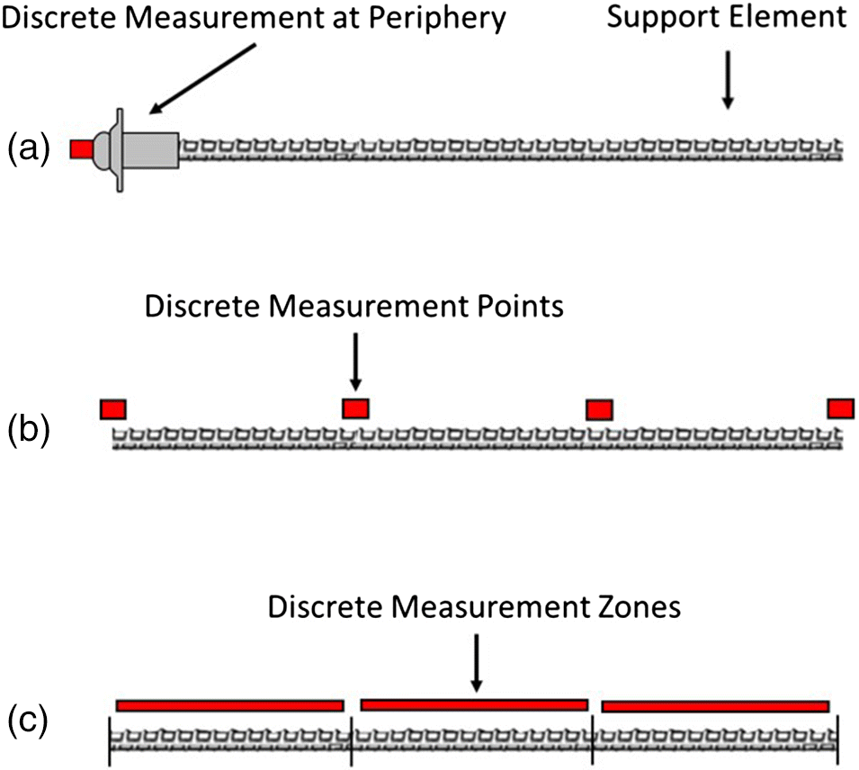
The most common approach to an intrinsic sensing solution for support members has involved the use of discrete sensing techniques. Examples include electrical-resistive strain gauges (e.g., Farmer 1975; Serbousek and Signer 1987), load cells (e.g., Rodger et al. 1996; Mitri 2011), long base-length induction gauges and displacement transducers (e.g., Choquet and Miller 1988; Spearing et al. 2013), and inclinometers (e.g., Volkmann 2003). Using these sensing techniques, the support member under study is effectively discretized into a number of discrete (or individual) measurement points or zones depending on the gauge length of the chosen sensor (see Fig. 2). The spatial resolution or density of measurements along the length of the support member will be controlled by the number of discrete sensors that can be applied to a given support member. This will ultimately be limited by the increased cost and manufacturing difficulties of adding more measurement points. Consequently, the capability of a discrete monitoring solution to measure the behaviour of a support member will be contingent upon load-inducing events occurring within the region of a discrete measurement point or uniformly across a discrete measurement zone. This is most significant when the ground behaviour is discontinuous in nature (Björnfot and Stephansson 1983; Hyett et al. 1996; Li and Stillborg 1999). Realizing the spatial limitations of conventional discrete sensing solutions, it is necessary to consider innovative strain-sensing techniques such as FOS.
Fig. 2.
Fiber optics was originally proposed as an improved method for the communications industry in the 1960s (Kao and Hockham 1966), replacing copper wire and electric current with a glass optical fiber and light, respectively. The optical fiber is composed of a high-quality, fused-silica core surrounded by silica cladding with a lower refractive index that acts as a dielectric waveguide, achieving much lower attenuation rates (Keck and Schultz 1970). However, external perturbations that cause physical changes to the optical fiber (e.g., temperature and strain) will also disturb the propagating signal within. In this manner, an optical sensor can be realized by determining a relationship between the physical change of the optical fiber and the spectral shift of the signal (i.e., amplitude, frequency, and phase). This provides an intrinsic solution whereby the optical fiber itself acts as both a transmission medium and transducer. Current commercially available solutions that can determine changes in strain and temperature locally along a micrometer-scale, single-mode optical fiber include fiber Bragg grating (FBG) and DOS techniques. The fundamental working principles of these techniques are discussed to provide a rationale for choosing the most applicable technology for the application of monitoring ground support members.
FBG
A Bragg grating is fundamentally a fixed refractive index modulation of an optical fiber core acting as a dielectric mirror (Venghuas 2006). Bragg gratings are commonly produced by laterally exposing a fiber core to a periodic pattern of ultraviolet light. The exposure results in the fabrication of phase structures directly into the optical fiber core, which results in a permanent change of the refraction index at exposed sections (Meltz et al. 1989; FBGS 2017). An example Bragg grating is displayed in Fig. 3. The incident light spectrum (i.e., the input light) will be partially reflected along the Bragg grating structure. At a particular wavelength, the back-reflected signals will be combined in a coherent fashion. This wavelength is termed the Bragg wavelength (λBragg) and will have a centered wavelength position per the spacing of the grating structures (Λ) and the refractive index of the single-mode optical fiber (neff), eq. (1).All other wavelengths forming the incident light will pass through the Bragg grating structure unaffected.
(1)
Fig. 3.
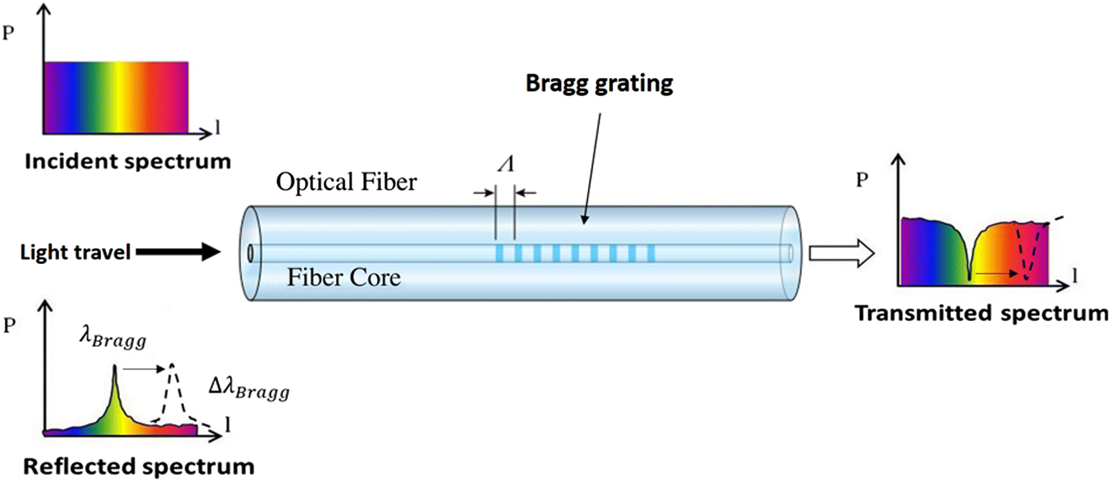
Strain and temperature perturbations to a Bragg grating structure will alter both the refractive index and the periodicity of the grating structures. In this manner, the center position of the reflected Bragg wavelength will also be influenced by external disturbances that result in change in the length or temperature of the optical fiber. The shift of the Bragg wavelength (ΔλBragg) resulting from strain being applied to the optical fiber can be determined according to eq. (2), where l is the specimen length.In a single-mode optical fiber, the shift of the Bragg wavelength will respond linearly with applied strain (ε). A dimensionless gauge factor (Fg) for the strain to Bragg wavelength shift can be determined according to eq. (3) (Micron Optics Inc. 2012).
(2)
(3)
For conventional silica optical fibers, the gauge factor will be a value within the range of 0.75–1.3 (Haase 2007; Black et al. 2008; FBGS 2015). In this manner, the initial, unperturbed Bragg wavelength can be recorded as a reference measurement to compare with future conditions whereby a shift in the Bragg wavelength can be used to determine strain across the Bragg grating with microstrain accuracy. FBGs are optically analogous to conventional electrical strain gauges as a single strain measurement is obtained per transducer. However, a distinguishing feature of the FBG technique is that the transducer (i.e., the optical fiber) is also the lead. Furthermore, multiple Bragg gratings can be multiplexed into a single fiber, such that one optical fiber is used to monitor an array of locations along the fiber (Davis and Kersey 1994). Yet, it is important to note that the FBG technique fundamentally remains a discrete solution as a limited number of Bragg gratings can be inscribed into an individual sensor, and a limited number of strain measurements can be taken along the optical fiber.
The maximum number of Bragg gratings will be dictated by numerous factors, including manufacturing limitations (e.g., the precision of the UV laser source), the sensor length in comparison with the Bragg grating length, and the demodulation technique used to interpret the reflected signal. The most common demodulation technique is wavelength division multiplexing (e.g., Zhang et al. 1995; Araújo et al. 1998). This requires that each Bragg grating be manufactured to reflect a different Bragg wavelength (or reflect a unique wavelength with respect to other Bragg gratings). FBG interrogation units (e.g., the sm125 produced by Micron Optics Inc.) will generally implement a swept wavelength technique, where the incident light wavelength spectrum will be tuned through a set range of wavelengths (often in the range of 1510–1590 nm). This implies that there is a limited wavelength spectrum that can be reflected by the Bragg gratings. For example, considering a gauge factor of 1 and an initial reflected Bragg wavelength of 1550 nm, a 2 nm Bragg wavelength shift would correspond to approximately 1300 microstrain according to eq. (3). In terms of monitoring ground support members, strains well over 10 000 microstrain (i.e., 1% strain) can be expected. Care must be taken that Bragg gratings are not manufactured within a spectral proximity such that shifted Bragg wavelength will be prone to overlapping or reflecting the same Bragg wavelength as subsequent Bragg gratings.
DOS
DOS techniques utilize the back-reflected component of the light-scattering phenomenon that occurs continuously along the length of an optical fiber. Contrary to FBG techniques, DOS techniques do not require the spectral measurement to be induced (i.e., modification of the optical fiber in the form of Bragg gratings). Scattering is a spontaneous, diffuse reflection that is a result of Raman, Brillouin, and Rayleigh mechanisms. A change in local strain or temperature along the fiber will induce a modulation of the scattered signal (amplitude, phase, and frequency), which can be realized spatially along an optical fiber through optical time domain reflectometry (OTDR) and optical frequency domain reflectometry (OFDR) methods. The quintessential distributed sensor would provide a continuous strain profile (i.e., infinite measurement points) along the length of an optical fiber. In reality, the spatial resolution will be controlled by the technological limitations of the selected technique. Ultimately, the pulse width of the laser source (τ) and the frequency-scanning range of the laser source (ΔF) will dictate the spatial resolution (Δz) of OTDR and OFDR techniques, respectively. These relationships are described by the following equations (Kingsley and Davies 1985; Froggatt et al. 2004), where c is the speed of light in the optical fiber core and ΔF is further dependent on the center wavelength (λ) and the wavelength bandwidth (Δλbw).It is important to note that an inverse relationship exists among the spatial resolution, measurement repeatability, and maximum sensing length. For example, the pulse width using OTDR can be increased to improve the maximum length of the sensor, but this will coarsen the spatial resolution according to eq. (4). Similarly, the repeatability may be increased by taking an average of a series of local measurements, but this makes the spatial resolution coarser.
(4)
(5)
(6)
The fundamental working principles of Brillouin- and Rayleigh-based DOS techniques are discussed in further detail within the following sections. Raman scattering-based techniques have been excluded from the following discussion as the respective scattering is primarily temperature dependent (Dakin et al. 1985).
Brillouin optical time domain reflectometry (BOTDR)/Brillouin optical time domain analysis (BOTDA)
BOTDR and BOTDA are two DOS techniques that measure the Brillouin scatter frequency shift along a low-cost, single-mode optical fiber. BOTDR monitors spontaneous Brillouin scatter, an inelastic phenomenon corresponding to a frequency-shifted component of the input light that is attributed to the effective refractive index of the optical fiber and the interaction of optical (i.e., photon) and acoustic (i.e., phonon) waves in the optical fiber (Agrawal 2001). The frequency of the Brillouin scattering (vb) will be maximum according to eq. (7), where Va is the acoustic velocity in the optical fiber.Strain and temperature perturbations to the optical fiber will shift the frequency of the Brillouin scatter. This shift predominately arises from the change in acoustic velocity from the density of the fiber core being modulated. The shift of the Brillouin frequency has a linear relationship with applied strain according to eq. (8) (Horiguchi et al. 1989).A strain constant (Cε) of 4.4 is regularly quoted for silica optical fibers and has been found not to vary significantly for various material compositions (Shibata et al. 1988). As Brillouin scattering occurs continuously along the length of an interrogated optical fiber, a distributed sensor can be realized by measuring the unperturbed Brillouin frequency and comparing it with the Brillouin response at a later time. The Brillouin frequency is resolved spatially along the fiber by monitoring the return time of the signal and knowing the speed of light in the optical fiber (i.e., OTDR).
(7)
(8)
Monitoring the spontaneous Brillouin response (i.e., BOTDR) allows measurement of strain over kilometer lengths of optical fiber (Kurashima et al. 1989; Shimizu et al. 1993); however, the low-level detected signal (i.e., the Brillouin frequency) limits the spatial resolution to >1 m, even though Brillouin scattering occurs continuously along the fiber. This also constrains the accuracy of the strain measurement and acquisition rate, especially when long sensing lengths are considered. However, the low-level signal response may be overcome by stimulating the Brillouin scattering process, which amplifies the signal. BOTDA (Horiguchi and Tateda 1989a; Niklès et al. 1996) stimulates acoustic waves in an optical fiber sensor by injecting two counter-propagating waves. This requires access to both ends of the optical fiber to launch both a pulsed signal (i.e., a pump laser) and a tunable counter propagating continuous wave (i.e., a probe laser) (Fig. 4). When the frequency difference between the pump and probe signal is equal to the Brillouin frequency, eq. (7), a resonant condition will be established and Brillouin scattering will be stimulated at the respective position along the optical fiber. The amplified signal from the probe carries local strain information (i.e., eq. (8)) back to a receiver at a comparatively stronger signal than the BOTDR technique while also carrying time domain information from the pulsed signal (Horiguchi and Tateda 1989b; Bao et al. 1994). The amplified signal allows the BOTDA technique to measure strain at comparatively better spatial resolution, accuracy, and length than the spontaneous counterpart (i.e., BOTDR). Two commercially available BOTDA systems are the Neubrexcope-6000 (Zhang and Wu 2007) and the DITEST STA-R (Omnisens 2014). The former is capable of measuring strain at a spatial resolution of 10 cm over a maximum optical fiber length of 1 km and accuracy of ±25 microstrain. The latter is capable of a strain accuracy of ±1 microstrain, although this reduces the maximum sensing length to 50 m and the spatial resolution to 0.5 m. Alternative technologies that incorporate BOCDA or BOCDR have demonstrated 70 mm spatial resolution at 1 km sensing length (Hotate et al. 2008), 1.6 mm spatial resolution at 10 m sensing length (Song et al. 2006), and sampling rates of 5 kHz (Hotate et al. 2012); however, these technologies are still under development, with a limited number of prototype units field tested (e.g., Saito et al. 2014).
Fig. 4.

Rayleigh optical frequency domain reflectometry (ROFDR)
Rayleigh scattering is a spontaneous loss mechanism arising from random fluctuations of the refractive index fused into the silica core of an optical fiber from the manufacturing process. This is not to be confused with intentional index variations as discussed for the FBG technique. Similar to FBG, local strain and temperature change to the optical fiber will lead to an alteration of the local refractive index and the Rayleigh scatter signature. Unlike Brillouin scattering, Rayleigh scattering is elastic, resulting in virtually no frequency change when comparing the incident light and light scattered via the Rayleigh mechanism. Techniques implementing OTDR to capture Rayleigh scattering require high-powered (costly) lasers and long acquisition times to obtain comparable sensing lengths, accuracies, and spatial resolutions with the aforementioned Brillouin techniques (Lu et al. 2010). However, Froggatt and Moore (1998) have discussed the potential for using the Rayleigh scatter frequency response (i.e., OFDR) to measure strain with an interferometric technique that compares the path length difference between a measurement and reference arm (Fig. 5).
Fig. 5.

ROFDR monitors the amplitude and phase of Rayleigh scatter as a laser source is spectrally tuned through a range of frequencies. This provides a description of the Rayleigh scatter profile in the frequency domain over many sub-millimeter sections along the given optical fiber. Using a Fourier transform, the discretized sections of optical data are converted to the time domain, which allows the physical location of local scatter to be determined according to the time of flight of light in the optical fiber. The ambient Rayleigh signature is stable and unique to a given optical fiber (Froggatt et al. 2004). This is stored as a reference measurement or state. The spectral shift associated with strain or temperature change at a later point is determined through a cross-correlation of the reference and perturbed state (Froggatt and Moore 1998). Local strain will be manifested as a shift in the cross-correlation peak (Δλ) according to eq. (9).For silica optical fibers, a strain calibration constant of 0.78 can be used; however, this may vary by approximately 10% depending on the optical fiber composition (Kreger et al. 2007). ROFDR can achieve spatial resolutions <1 mm in addition to comparable strain accuracies as the FBG and Brillouin-based techniques. However, the maximum sensing length is limited to 40 m due to system noise associated with the laser and the low reflected power of the Rayleigh signal.
(9)
Distributed fiber Bragg gratings (DFBGs)
ROFDR utilizes a standard (i.e., unmodified) single-mode optical fiber and measures low-level scatter associated with inhomogeneities in the index profile of the fiber. However, backscattered/reflected light that is intentionally induced by writing FBGs into the core of the optical fiber can also be measured using OFDR as the demodulation technique (e.g., Kreger et al. 2013), essentially providing a DFBG solution. This results in a significantly more powerful measured signal that allows long lead lengths (kilometer scale), a ±1 microstrain accuracy, and fast acquisition rates (250 Hz). But this also requires FBGs to be continuously written along the length of the optical fiber, compromising the spatial resolution (>6.35 mm) and the sensor cost.
Applicability to ground support
The working principles of commercially available FBG, BOTDR/BOTDA, ROFDR, and DFBG units have been discussed to provide a rationale for selecting the most applicable FOS technique to measure strain of ground support members. Table 1 provides a summary of operational features for each FOS technique.
Table 1.
| Technique | FBG (Micron Optics Inc. 2012; FBGS 2015) | DFBG (Luna Innovation Inc. 2017; Sensuron 2017) | BOTDR/BOTDA (Omnisens 2014) | ROFDR (Luna Innovation Inc. 2017) |
|---|---|---|---|---|
| Maximum sensing length | >1000 m | <52 m | >1000 m | <40 m |
| Measurement repeatabilitya | ±0.1–10 με | ±1 με | ±1 με | ±5 με |
| Spacing of measurements (i.e., spatial resolution) | 0.10 m (practically) | 6.35 mm | 0.10–1 m | 0.65 mm |
| Maximum number of measurement points | 10–20 (practically) | >1000 | >1000 | >1000 |
| Sensing range | ±17 500 με | ±30 000 με | ±30 000 με | ±30 000 με |
| Acquisition time | <1000 Hz | <250 Hz | <1 Hz | <60 Hz |
| Unit price (approximate USD) | $15 000–$125 000 | >$70 000–$125 000 | $100 000–$250 000 | $60 000–$150 000 |
| Sensor price (approximate USD) | ∼$300–$1000 per sensor | ∼$300–$5000 per sensor | $0.10 per meter of fiber | $0.10 per meter of fiber |
| Maximum number of connected sensorsb | >10 | 8 | 2 | 1 |
a
Repeatability will ultimately be related to the level of strain experienced by the optical sensor. At higher strain levels (>10 000 με) repeatability will decrease.
b
Maximum number of connected sensors without the purchase of an additional switch unit.
An immediate consideration is the optical fiber to be used as the sensor. All FOS techniques use a single-mode optical fiber as the transducer and lead; however, the FBG and DFBG techniques require additional manufacturing complexities to permanently inscribe Bragg gratings into the optical fiber core. This brings forth two distinct issues: (i) the sensor price will be significantly more expensive than a standard optical fiber and (ii) the sensors must be individually addressed and designed per order (i.e., spacing of Bragg gratings). Yet the most substantial consideration is the choice between FBG and the DOS techniques. FBG provides a discrete sensing solution with a limited number of practical sensors per optical fiber. Therefore, FBG will be susceptible to the same spatial resolution concerns as electrical discrete-sensing techniques. For this reason, a DOS solution is preferred.
An apparent compromise exists among spatial resolution, accuracy of strain measurements, and maximum sensing length. This compromise is also apparent when comparing the Brillouin-based and Rayleigh-based (i.e., DFBG, ROFDR) DOS techniques. Both sensing techniques can achieve relatively similar strain accuracies, but BOTDR/BOTDA can monitor significantly longer lengths, whereas ROFDR and DFBG can monitor finer spatial resolutions. A decision between Brillouin-based and Rayleigh-based DOS must be based upon the fundamental requirements of an ideal support member monitoring technique. Previous efforts have indicated that the most pertinent shortcomings of conventional instrumentation have been in the increased costs and manufacturing difficulties associated with providing an adequate spatial resolution to capture the geomechanistic response of a given support member. The length of the rock bolt, UA, and cable bolt support members considered in this research are often between 1 and 10 m long. Accordingly, the sensing-length limitations of the Rayleigh-based DOS techniques are nullified, and the superior spatial resolution is advantageous for measuring localized behaviour. However, it should be noted that the Brillouin-based DOS techniques are certainly of intrigue to larger geomonitoring projects, including slope stability (e.g., Shi et al. 2006), tunnel deformations (e.g., Moffat et al. 2015), geotextile performance (e.g., Habel and Krebber 2011), and pipeline monitoring (e.g., Inaudi 2005).
Within the context of monitoring ground support members, the choice between DFBG and ROFDR is primarily dictated by measurement rate and lead requirements. The induced (i.e., amplified) Rayleigh signature provided by the DFBG technique allows significantly faster measurement rates and longer leads lengths to be used, but it also requires a much more expensive optical fiber segment for the transducer. The initial verification experiments proposed in this research effort will consider controlled laboratory conditions and relatively static loading increments. In addition, it is anticipated that an abundance of optical sensors will be required to design such a technique. Cost per sensor is perhaps the most burdensome contrast between the two techniques. Accordingly, ROFDR was selected. The sub-millimeter spatial resolution measured with the ROFDR technique also provides the best potential to both identify and capture local and micro-scale ground support response mechanisms. However, the ability to measure only a single optical sensor is a drawback to the selected technique. The assessment of ROFDR for monitoring ground support members must identify whether the 0.65 mm spatial resolution is beneficial enough to outweigh the limitations of the technique.
Application of FOS to ground support members
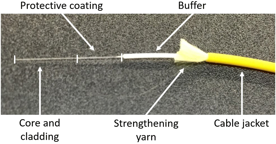
The design and application of a technique that couples FOS with ground support members is a nontrivial undertaking. Conventionally, optical fiber design has been aimed at providing the best protection from external influences (i.e., strain and temperature) to optimize signal transmission. In contrast, FOS requires loading of the specimen of interest to be directly transferred to the optical fiber. Ground support requires a strong bond between the active sensing length of optical fiber cable and the given support member. The general construction of a single-mode optical fiber cable (Fig. 6) consists of a high-quality fused silica core (9 μm) and cladding (125 μm), a protective coating (250 μm), buffer (900 μm), strengthening yarn, and cable jacket (>1 mm). The buffer, strengthening yarn, and cable jacket are not directly bonded to the optical fiber core cladding and inhibit strain transfer. Conversely, the protective coating is often applied directly to the core cladding during the optical fiber drawing process, physically bonding it.
Fig. 6.
Depending on the application, ground support members can be expected to experience strains well over 1% (i.e., in excess of 10 000 microstrain); however, the scope of this research is to validate the technique primarily within the elastic response of steel support members (i.e., <2500 microstrain) under a controlled laboratory setting. For this reason, the active optical sensing length will only make use of the core/cladding/protective coating assembly, although dampening the strain transfer through additional protective layers may have potential for use with yielding support members (e.g., Li 2012). Within this context, the goal is to have the optical fiber sensor strain directly with the given support member. Regarding the selected ROFDR technique, an optical sensor constitutes an optical fiber length that has been terminated with a connector and a nonreflective termination at opposing ends. The discussions herein have considered a lucent connector (LC) with an angled polish finish and a bend-insensitive optical fiber as recommended by Luna Innovation Inc. (2017). An acrylate protective coating has also been selected for its ideal strain transfer properties, ease of stripping (for optical splicing of termination segments), and low cost. It has been noted that a more costly polyimide protective coating is preferred for long tests (>1 year) and diverse temperature ranges (Inaudi et al. 1996), but this does not fall within the scope of the research presented herein. However, the technique developed using an acrylate protective coating can be directly transferred to a polyimide-coated optical fiber.
Three support member typologies have been considered in developing the FOS technique: (i) rock bolt support, (ii) UA support, and (iii) cable bolt support. The physical geometries, installation procedures, and assumed loading behaviour of these support members are believed to provide an ideal scheme for transferring the technique to other support members. The methods taken to bond, protect, and validate/calibrate the FOS technique for these support members are discussed within this section.
Rock bolt support
Rock bolting is a very common technique used to support excavations in rock for both mining and civil applications. The element itself normally constitutes a solid or tube-formed steel member that is inserted into a borehole, coupled to the rock mass using either a mechanical expansion anchor or an encapsulating cementitious/resin grout, potentially fastened to the excavation surface using nut and face plate assembly. The steel element may be installed untensioned or tensioned within the rock mass (Stillborg 1994). There are many rock bolting variations that can be deployed in a given project, but the support type is perhaps most associated with the use of fully grouted steel rebar (i.e., a solid steel rebar that is fully encapsulated within a rock borehole).
There are two general methods that have been considered to couple either conventional strain sensors or FOS with rock bolt support: (i) external coupling (e.g., Farmer 1975; Schroeck et al. 2000) and (ii) internal coupling (e.g., Serbousek and Signer 1987; Iten and Puzrin 2010). External coupling involves surface mounting the sensor to the rock bolt (e.g., ASTM E1237-93 2014) consequently leaving the sensor and leads exposed. Surface mounting could possibly withstand controlled laboratory testing, but the preferred solution should have the potential for further in situ use. An internal solution, whereby the sensors are confined within the rock bolt, is preferred, but this solution must not significantly alter the capacity or behaviour of the rock bolt itself. Using a standard #6 grade 60 rebar (i.e., 19.05 mm diameter, 120 kN minimum yield) has been approached by machining out a 2.5 by 2.5 mm lengthwise groove to embed and encapsulate an optical fiber with a proprietary adhesive. The groove dimension provides ample space for the optical fiber to be situated below the exterior profile of the rebar but, more importantly, it provides a protective barrier once encapsulated. However, care must be taken to run the optical fiber straight within the groove to avoid potential orientation difficulties if more than one groove is to be analyzed (Forbes et al. 2017). A comparison between several different bonding agents was discussed by Forbes (2015).
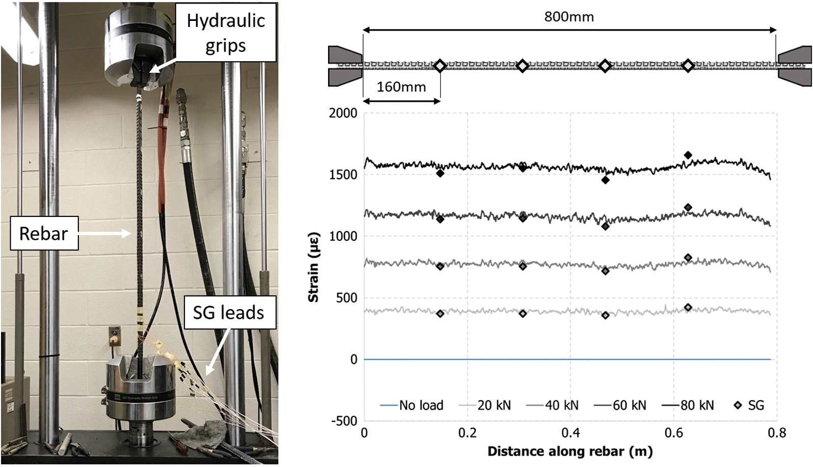
The rebar members used in this research were modified with a pair of diametrically opposed grooves. A single optical fiber sensor was used to monitor both grooves (roughly 4% reduction in the cross-section area) by looping the sensor within a machined groove that connected the diametrically opposed grooves at one end of the rebar (Fig. 7). This provides both a redundancy measure and a method to compensate for bending-induced strain (Hyett et al. 2013; Forbes et al. 2017). Validation of this FOS technique was accomplished by conducting an end-loaded, elastic tensile test with an 800 mm testing span using a 500 kN servo-controlled loading frame. In addition to the ROFDR, electrical resistive strain gauge pairs (i.e., on opposing sides of the rebar) were surface mounted every 160 mm along the testing span. A comparison of the averaged strain at various levels of applied load is presented in Fig. 8. This is the bending-compensated strain according to eq. (10).The ROFDR provides a strain profile (i.e., strain distribution along the rebar) at each loading increment as strain is measured at a spatial resolution of 0.65 mm. Conversely, each electrical strain gauge provides a single measurement point over its 3 mm gauge length. The difference in measured strain between the two techniques did not exceed 5.0% in a total of three validation tests. In addition, the strain measured with ROFDR was within 3.5% of the theoretical rebar strain value at each load increment.
(10)
Fig. 7.

Fig. 8.
UA support
The UA is a temporary support system forming a structural umbrella around the excavation from the insertion of longitudinal support members installed from within the tunnel above and around the crown of the tunnel face (Oke et al. 2014a). The UA is often considered a presupport technique as the support members are installed prior to the first pass of the excavation. According to the nomenclature developed by Oke et al. (2014b), the longitudinal support members can be broken down into three main support element categories:
i.
forepoles: element length greater than the height of the excavation, installed at shallow angles to the tunnel axis (commonly a 114 mm diameter steel pipe);
ii.
spiles: element length smaller than the height of the excavation, primarily installed to controlled structurally driven failure (commonly a sub-30 mm diameter steel bar); and
iii.
grouting elements.
From these categories, the forepole element has been selected as the focus of the UA FOS technique. A standard 114.3 mm outer diameter Gr. B steel (ASTM A53/A53M-12 2012) pipe with a 6.02 mm wall thickness was chosen for the forepole element in this research (a commonly used pipe size in industry). The hollow cross-section of this steel member adds an inherent difficulty to the FOS technique. Considering the aforementioned rock bolt technique, a 2.5 mm deep groove is approximately 41.5% the thickness of the pipe and would notably impact the strength capacity. Additionally, the hollow cross-section prohibits the optical fiber from being looped at one end while still residing below the exterior profile of the pipe. Therefore, to conduct an initial proof of concept, it was decided to surface mount (ASTM E1237-93 2014) the optical sensor to the exterior pipe surface along a single length. Surface mounting to the interior pipe profile was considered (e.g., O’Looney 2009; Vishay Precision Group 2010; Landers and Philips 2014), but the reduced accessibility was believed to hinder the reliability in bonding the optical sensor and in assessing the merit of the ROFDR technique. Furthermore, an interior surface-mounting technique is not believed to provide a feasible solution for future in situ development as forepole members are predominately installed as a self-drilled member (i.e., installed with a sacrificial drilling bit and requiring the hollow interior for debris flow, water, and grout). Interior surface mounting is considered an unnecessary complication.
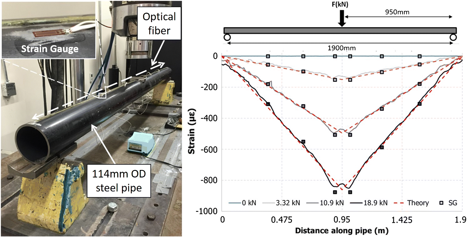
In conducting an initial validation of this optical technique, it was decided to laterally load a forepole specimen under a symmetric bending configuration using a 500 kN servo-controlled loading frame. Bending provides the most controlled method for establishing the baseline accuracy of the optical technique with the forepole element as comparatively low loads are required to deflect, rather than coaxially stretch, the steel member. As displayed in Fig. 9, load was applied to the forepole at the center point between two roller supports spaced approximately 1900 mm apart. The optical sensor was aligned along the top axis of the forepole member to measure compressive strain (as the rock bolt validation measured tension) in addition to six surface-mounted electrical resistive strain gauges. The sensor alignment necessitated a platen piece to apply load to the forepole member to avoid directly loading the optical sensor itself. The plot in Fig. 9 displays a comparison of the strain measured using the ROFDR technique, electrical resistive strain gauges, and theoretical strain distribution according to Euler–Bernoulli beam theory. Like the initial rock bolt test, the difference in the strain measured (or predicted) did not differ by >5.0%. In addition, the influence of the platen piece at the loading position was discernable in the ROFDR strain distribution and presented the largest source of discrepancy among the three methods.
Fig. 9.
Cable bolt support
A cable bolt support element normally consists of a seven steel-wire strand (i.e., six steel wires layered in a helical configuration around a central steel wire) that is installed and cement grouted within the borehole and used to support a given excavation like the aforementioned rock bolting technique. The helical composition of the cable bolt gives the element a significantly lower torsional rigidity than a solid bar or tube element of the same nominal diameter and allows the element to be placed on a reel after the manufacturing process. This allows for long lengths of this support member (i.e., in excess of 10 m) to be easily transported and installed, even within small excavation confinements. However, this helical composition also provides an additional complexity in applying the optical sensor. Choquet and Miller (1988) have discussed an external-tension measurement technique in which spiral resistance wire is wound into a flute (i.e., the notch between adjacent strands at the exterior profile) of the cable bolt, but this would require extensive protection measures to replace with an optical sensor (which also dampens strain transfer). Additionally, the external profile of the cable bolt (i.e., the flute geometry) has been noted to be very influential on the support member’s behaviour and capacity (Hyett et al. 1992). Therefore, it is preferable to couple the optical sensor within the central, straight steel wire in a similar technique for discrete displacement sensors as discussed by Hyett et al. (1997). This considers replacing the central wire of the cable bolt with a hollow tube of the same diameter to house the optical sensor. Load is transferred to the central tube via a frictional relationship with the outer six wires. Considering FOS, this was approached by first straightening (by applying a slight tension) and centering an optical fiber within a stainless steel tube and then fully encapsulating the optical fiber using a two-part epoxy resin. Once cured, the given cable bolt is opened to remove the central wire and then rewound with the optically instrumented tube (Fig. 10). The tests discussed within this research have considered a 14.3 mm nominal diameter, low-relaxation steel strand (ASTM A416/A416M-17 2017).
Fig. 10.

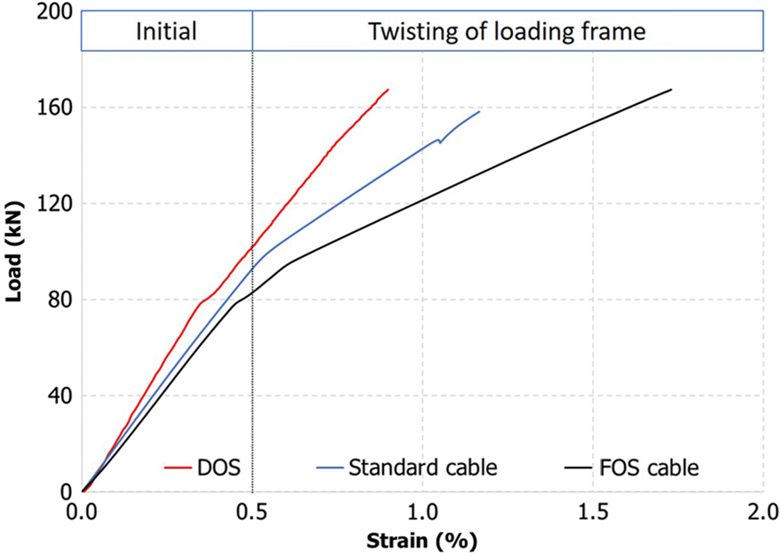
The central wire of a cable bolt is shorter than the wrapped outer six wires and will take on more strain per displacement of the surrounding rock mass. This necessitates a calibration of the measured strain along the central, optically instrumented tube with the load of the full cable bolt. A tensile test arrangement using the same loading frame as discussed for the rock bolt validation test (Fig. 8) was selected for the calibration but with minor adjustments to accommodate standard strand-testing protocols (ASTM A1061/A1061M-16 2016). The test was conducted on both a standard cable bolt and an FOS cable bolt. Actuator load and displacement were measured for both cable bolt types in addition to measuring strain with the optical sensor for the FOS cable bolt. A comparison of the load–strain relationships for the standard cable bolt and the FOS cable bolt using both the actuator displacement and optically measured strain is displayed in Fig. 11. Below 0.5% strain on the central wire/tube, the load–strain trend of the standard cable bolt and FOS cable bolt differs by approximately 1.05%. This implies that initial elastic behaviour of the strand is not significantly impacted by the replacement of the central wire. Above 0.5% strain, the load–strain relationship between the two cable bolts begins to deviate, concurrent with a notable change in the slope of the profiles. This slope change corresponds with a torsional resistance limitation of the selected loading frame. At approximately 0.5% strain for both cable bolt types, the hydraulic gripper assembly (see Fig. 8) began to rotate with increased applied load. This allowed the outer six wires to unwind, providing a less stiff response. For this reason, the FOS technique was calibrated using the initial 0.5% strain loading region. Comparing the three profiles, a load to measured strain relationship of approximately 0.020 kN/με was obtained.
Fig. 11.
Laboratory results
A comprehensive testing program was performed to assess the merits of the FOS technique. The program consisted of subjecting optically instrumented rock bolts, forepoles, and cable bolts to expected in situ loading behaviour through various laboratory arrangements. It should be noted that the intention of this experimental program is to demonstrate the capability of the FOS technique to capture expected support-member behaviour, rather than to conduct an intensive study of one particular mechanism. Within this context, the unprecedented insight provided by the FOS technique is discussed.
Rock bolt experiments
Fully grouted rock bolts (more specifically steel rebar) are predominately passive support elements. This implies that the majority of the bolt’s support capacity is mobilized as a result of subsequent rock mass movements. Therefore, the load–strain profile along the rock bolt will be controlled by the distribution of rock mass displacements once installed. In jointed and fractured rock masses, the rock bolt load distribution will most commonly be reflective of a number of localized discontinuity movements (Björnfot and Stephansson 1983; Hyett et al. 1996; Li and Stillborg 1999), which may act coaxial and (or) transverse to the bolt axis. In simulating this loading behaviour in the laboratory, two experimental arrangements were conducted: (i) coaxial loading and (ii) double shear-plane loading. The behaviour of the latter has been particular difficult to monitor with conventional strain techniques because of the locality of its effect on the bolt, often within 2.5–6.25 bolt diameters from the intersection of the bolt with the shearing plane (Ferrero 1995; McHugh and Signer 1999; Aziz et al. 2005; Grasselli 2005).
Coaxial loading
The most common in situ assessment of fully grouted support is perhaps the coaxial pull-out test (ISRM 1974, 1984; ASTM D4435-13e1 2013). This test consists of installing a rock bolt in agreement with the normal operational procedures at a given site and subsequently applying a coaxial load to the grouted support member from within the excavation. The pull-out test can be replicated under controlled laboratory conditions by replacing the host rock mass with a metal pipe, a simulated rock mass (e.g., concrete), or a cored rock sample, which provide a constant radial stiffness boundary condition. Accordingly, the assessment of the FOS rock bolt technique considered concrete (40 MPa UCS) block specimens (200 × 300 × 300 mm) and cylinder specimens (200 mm length by 300 mm diameter) with a preformed 31 mm diameter borehole. After allowing 28 d for the concrete to cure, the preformed boreholes were roughened and cleaned using a rotary drill. The FOS rebar was then centered within the borehole and encapsulated with a polyester resin grout (i.e., a 200 mm grouted length). The grouted rebar specimen was restrained to a servo-controlled loading frame, which was also used to apply coaxial load at a position 900 mm along the rebar from the concrete specimen. On the opposing side of the concrete block, the rebar was extended approximately 100 mm to allow potential slip of the rebar to be measured during the experiment. The coaxial loading apparatus is displayed in Fig. 12.
Fig. 12.
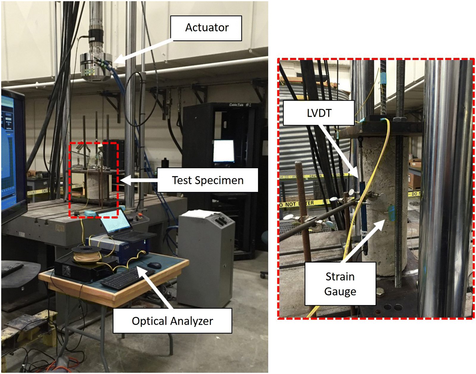
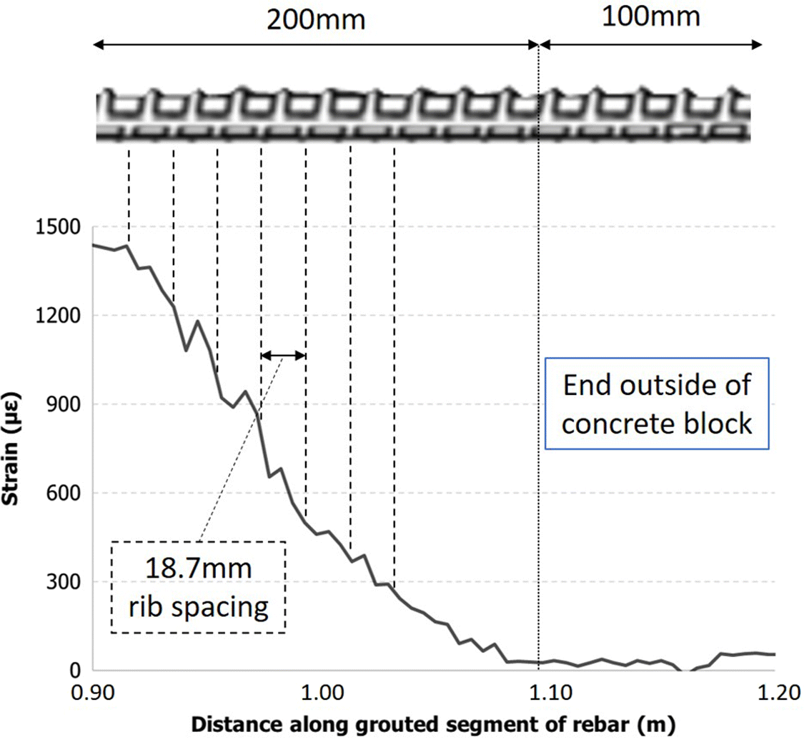
Figure 13 displays the bending-compensated strain measured along the rebar at 20 kN load increments. As discussed for the tensile validation experiment, this strain is obtained by taking the average strain from opposing sides of the rebar. The free length of rebar between the position of applied load and concrete specimen (i.e., 0.00–0.90 m) and the grouted segment of rebar (i.e., 0.90–1.10 m) are clearly distinguishable along the strain distribution. The free length of rebar is fundamentally an end-loaded coaxial arrangement and depicts a uniform level of strain at the given loading increment. This agrees well with the tensile validation experiment and the theoretical strain magnitude. This uniform strain decayed in an exponential form within the grouted section towards the unloaded end as discussed by Farmer (1975), Serbousek and Signer (1987), and Li and Stillborg (1999); however, a detailed examination of the grouted segment (Fig. 14) appears to provide a correlation between periodic disturbances in the strain profile and the spacing of the rebar ribs (roughly spaced by 18.7 mm). This would indicate that the FOS technique is capable of distinguishing the additional resistance provided by the individual rebar ribs within the grout (i.e., micro-scale geomechanisms). Such an effect has been discussed both analytically (e.g., Cao et al. 2014) and numerically (e.g., Jalalifar 2006), but never captured to such an extent.
Fig. 13.
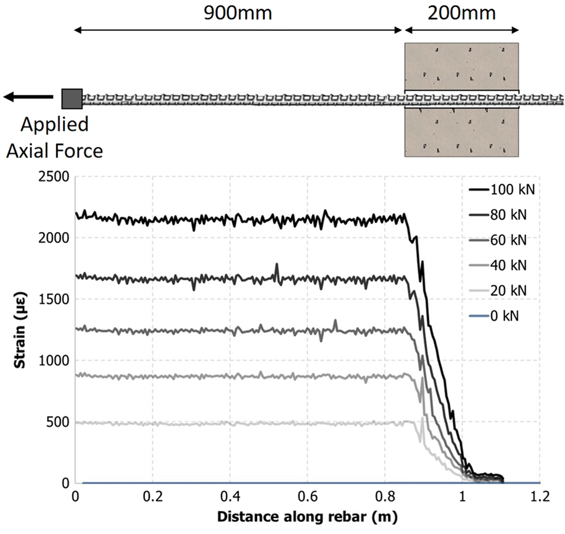
Fig. 14.
Double shear-plane loading
Shear displacement of a rock bolted discontinuity will rarely result in a direct guillotining of the steel member (Stillborg 1994). Instead the shear response of a grouted rock bolt will more commonly take on a combination of coaxial and bending-induced loads local to the discontinuity. This is often referred to as the “dowel” reinforcement effect (Spang and Egger 1990; Ferrero 1995; Grasselli 2005; Li et al. 2016). In testing the FOS technique under such conditions, a double shear-plane experiment was constructed. This consisted of centering and resin grouting an optically instrumented rebar into a 31 mm diameter reamed borehole that was precast through three individual concrete blocks (240 mm × 300 mm × 300 mm block dimensioning, 40 MPa UCS). The outer two blocks of this apparatus were restrained while a vertical load was applied to the central block using a servo-controlled 500 kN loading frame. A 5 mm thick nylon sheet was also placed between the blocks during the casting stage to promote a frictionless and nondilating surface for shear displacement. The result is two vertical shear planes acting along the bolt, providing a much less demanding apparatus to restrain than in a single shear-plane test (Aziz et al. 2003). The experimental apparatus as well the strain measured along the entirety of the optical sensor (i.e., both opposing sides of the rebar) are displayed in Fig. 15.
Fig. 15.
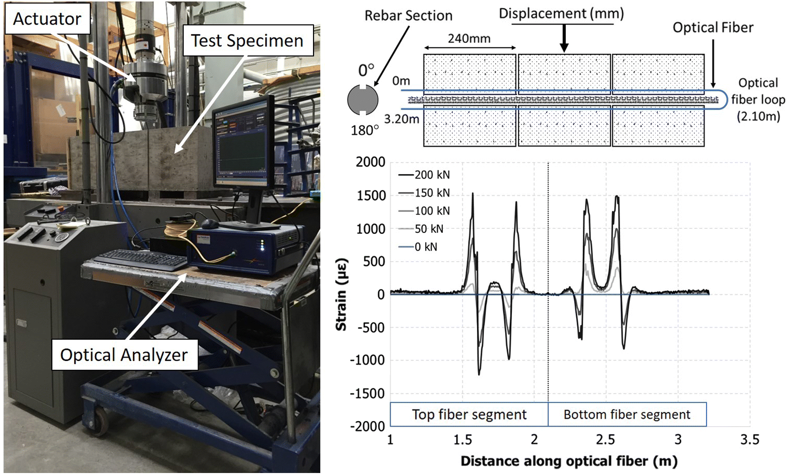
At each discontinuity (i.e., shear plane), a distinct shear couplet is measured. This corresponds to a pair of extensile (positive) and compressive (negative) strain concentrations that mirror at the shear displacement plane. However, the absolute strain magnitude of the compressive arm is less in each case. A possible explanation for this is the additional resistance provided by the grout on the compressed side of the shear plane and the relatively negligible adhesional resistance provided by the grout on the tensile side. This agrees well with previous research efforts in which the dowel-like response has been noted to result in “plastic-hinges” or an “S-bend” of the rock bolt at each discontinuity (e.g., Spang and Egger 1990; McHugh and Signer 1999; Aziz et al. 2005).
In this experimental setup, the strain appears to decay within 150 mm from the intersection with the discontinuity, although the peak strain is concentrated within 50 mm. This implies that a discrete sensing solution would require a fine concentration of sensors within close proximity of the discontinuity to detect the event. This is certainly obtainable under controlled laboratory conditions, but the precise location of such load-inducing discontinuities will not be known beforehand. Therefore, the strain distribution measured with the FOS technique was compared with an interpolated strain distribution obtained from electrical resistive strain gauges spaced at 250 mm increments (a very fine spatial resolution for such instrumentation in practice) along the same rebar specimen. The 0.65 mm spatial resolution measured with ROFDR was also compared with the hypothetical strain profiles obtainable with the other discussed FOS techniques by sampling the measured data in three ways: (i) taking one measured value from the ROFDR profile every 100 mm (equivalent to the measurement that would be provided by an FBG solution), (ii) taking an averaged value over 100 mm from the measured ROFDR profile (equivalent to the measurement that would be provided by BOTDR/BOTDA), and (iii) taking an averaged value over 10 mm from the measured ROFDR profile (3.6 mm coarser than DFBG would provide). The strain distributions measured along the top alignment of the rebar for both comparisons are displayed in Fig. 16.
Fig. 16.
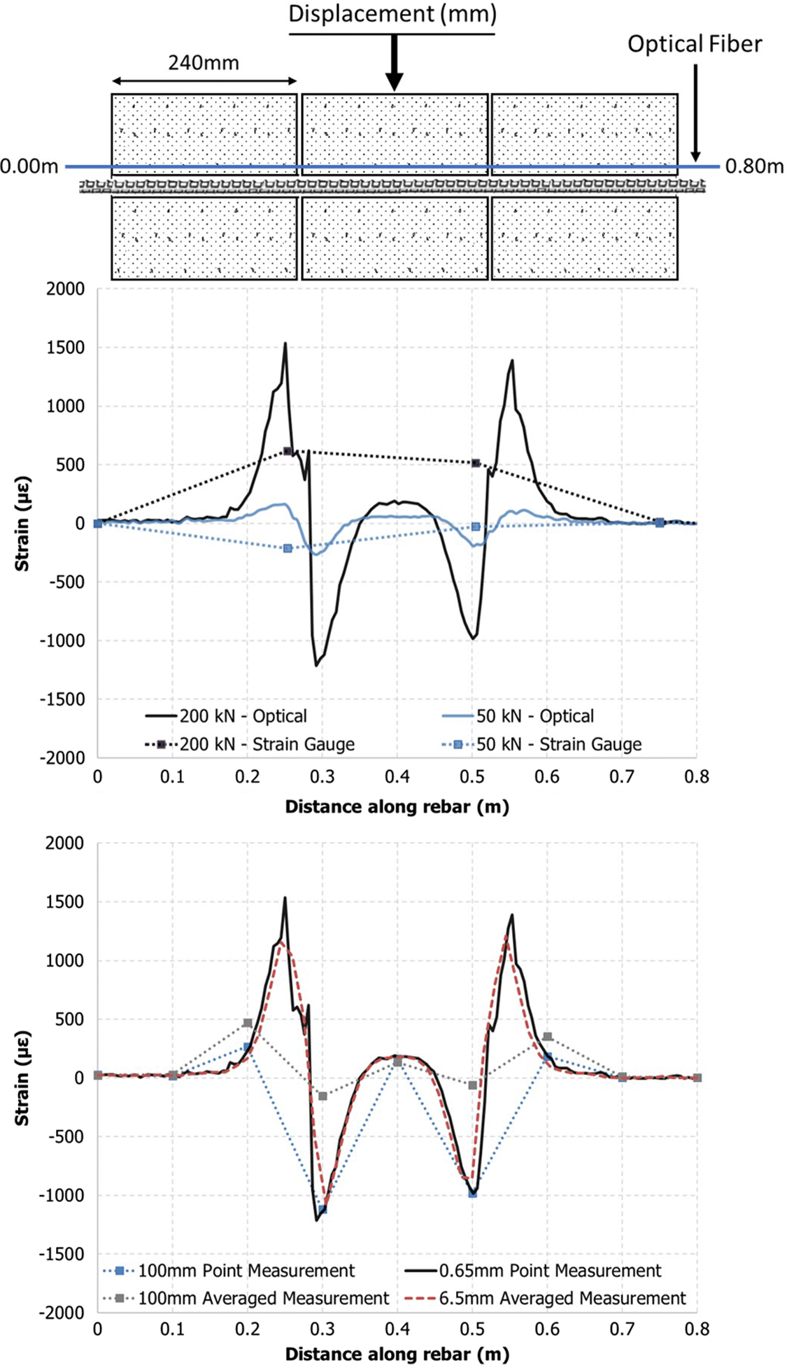
Comparing both the FOS technique and the strain gauge measurements, it is apparent that the coarse spatial resolution provided by the discrete sensing technique does not sufficiently capture the shearing mechanism. Furthermore, it suggests that it is completely fortuitous for such a discrete sensing technique to capture localized, discontinuous behaviour in situ. Drastically different strain profiles are also obtained for the two samplings at a 100 mm spatial resolution. At a 10 mm spatial resolution, the shearing mechanism is evident and the length of rebar influenced by the shearing displacement compares well with the ROFDR measurement; however, the peak strain magnitude along the rebar is slightly underestimated. This suggests that the DFBG technique would provide an adequate spatial resolution to measure localized support behaviour if the ROFDR technique’s limitations regarding the number of connected sensors and (or) lead lengths prohibit its use.
UA experiments
Forepole support members are passive elements activated by movements of the surrounding ground mass. Their primary support contribution involves the longitudinal transfer of load away from the region at and directly behind the active excavation face (i.e., the unsupported span). This is accomplished through bending of the forepole member, which will be founded on a stiff steel-set/concrete lining at both ends or steel-set/concrete lining and ground at the active excavation face depending on the construction stage. In this regard, forepole members will act as a multi-span beam for a majority of their serviceability life (John and Mattle 2002). The geotechnical and engineering properties of the ground mass as well as the steel-set/concrete lining will play a major role in the support contribution of the forepole member (Volkmann and Schubert 2007); however, this multi-span bending can be idealized as a symmetric bending experiment as discussed for the UA validation experiment. Within this context, the loading arrangement used in the validation test of the UA FOS technique was modified to accommodate bending spans ranging from 0.50 to 3.00 m (i.e., potential excavation advance lengths). A normalized plot of the strain profiles measured along the top alignment of various testing spans under 15 kN of applied load is presented in Fig. 17 (left).
Fig. 17.
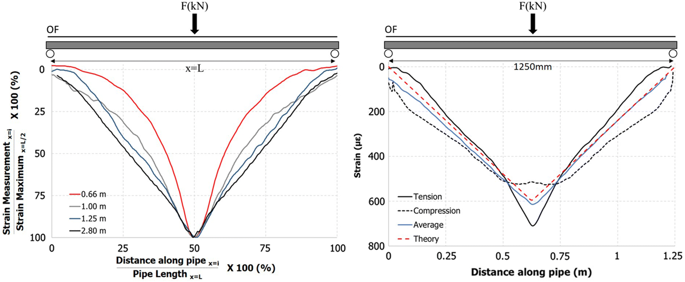
Euler–Bernoulli beam theory predicts a linear “V-shaped” strain profile for a point-loaded symmetric bending span. This strain profile corresponds to a parabola-like deflection profile of the forepole member. For the tested support spans >1.50 m, the measured strain profile agreed well with this theorized linear strain distribution. However, for shorter support spans, the measured strain profile was found to deviate from the expected linear response and instead concentrate within the region of applied load. This nonlinear trend intensifies with decreased testing span and, under given circumstances, resulted in measured strains nearly twice what would be expected from linear theory. A possible explanation for this nonlinear response of the steel pipe is the natural tendency towards flexural buckling or nonlinear elliptical behaviour (Timoshenko and Goodier 1951). Fig. 17 (right) shows this material response was further investigated through a 1250 mm span bending experiment with the optical sensor positioned along both the top (i.e., compressed) and bottom (i.e., tensile) alignment of the forepole member. The strain measured along the bottom alignment of the forepole member was both nonlinear and less than that predicted by linear theory. Furthermore, the difference between the predicted linear and measured nonlinear profile was greatest at the position of applied load and, correspondingly, the position of strain concentration along the top alignment of the forepole member. However, an absolute average of the strain measured along the top and bottom alignments of the forepole member obtained a strain profile nearly identical to that predicted by linear theory. It is also important to note that this nonlinear response was responsible for premature yielding along the compressed alignment of the forepole member.
Cable bolt experiments
Like rock bolting techniques, the coaxial pull test is commonly performed to assess cable bolt support capacity in both mining and civil excavations. This was approached under controlled laboratory settings by replacing the host ground mass with a 1500 mm long, 50 mm nominal diameter schedule 80 aluminum pipe (i.e., constant radial stiffness boundary condition). An FOS cable bolt was then centered and cement grouted (0.4 w:c ratio) within the aluminum pipe and allowed to cure for 21 d. Coaxial load was applied to the cable bolt using the same loading apparatus as described for the rock bolt coaxial test shown in Fig. 12. The strain distributions measured using the FOS cable bolt technique for incremental applied loads of 25 kN are displayed in Fig. 18. As discussed for the validation tests of the cable bolt FOS technique, this is the strain measured along the instrumented central tube and should not be confused with strain of the outer wires. As discussed by Hyett et al. (1996) and Li and Stillborg (1999), strain decays from the position of applied coaxial load towards the unloaded end of the cable bolt. However, the continuous strain distribution captured by the FOS techniques also allows the anchoring length (i.e., length of cable being strained) of the support member to be discerned. This is clearly shown to increase with increased applied coaxial load and corresponds with a nonsimultaneous failure of the cable bolt to grout interface (e.g., Kaiser et al. 1992). Although such a response is expected, it has previously been difficult to capture with the limited spatial resolution of conventional sensing techniques. Accordingly, many previous testing programs (e.g., Kaiser et al. 1992; Benmokrane et al. 1995) have focused on short grouted lengths (<200 mm) to permit the assumption of a uniform shear stress distribution across the cable bolt to grout interface. However, short grouted length experiments may not be representative of the actual behaviour of cable bolts installed in reality (grouted lengths rarely under 3 m).
Fig. 18.
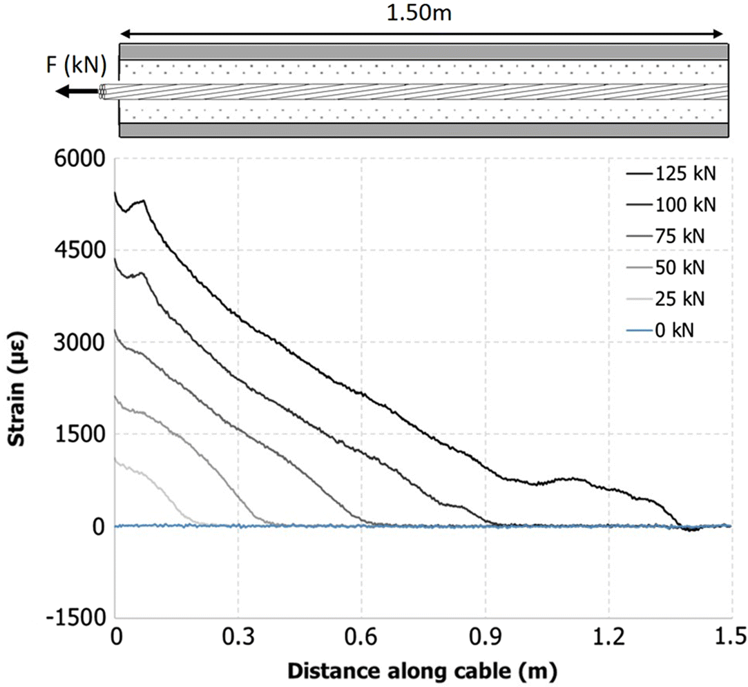
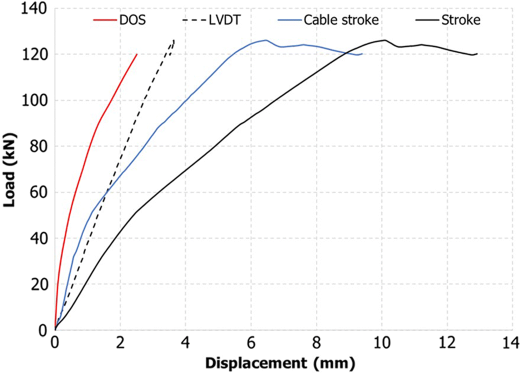
The capability to measure the entire strain distribution along the cable bolt’s length is also very advantageous for improving the coaxial load–displacement relationship of the support member. Previous testing programs (e.g., Hyett et al. 1992; Kaiser et al. 1992) have monitored the cable bolt (or rock bolt) apparatus external to the cable bolt–grout–rock apparatus. This includes: (i) load applied to the cable bolt outside of the grouted length, (ii) displacement of the cable bolt outside of the grouted apparatus (loaded and unloaded end), and (iii) displacement of the apparatus (if present). However, the strain distribution measured with the FOS technique can readily be converted to displacement (ux) according to eqs. (11) and (12).Figure 19 presents a comparison between the load–displacement relationships of the aforementioned cable bolt experiment for displacements measured from: (i) the stroke of the actuator (includes stretch of the free length of strand and apparatus deflection), (ii) the FOS technique (strain measured along central tube), and (iii) the apparatus deflection and the corrected stroke (obtained by subtracting the apparatus deflection and stretch of the free length of strand from the actuator stroke). The displacement measured by the FOS technique is significantly less than that measured by the actuator stroke and even the corrected stroke; however, the corrected stroke compared well with previous work (Hyett et al. 1992). This implies that previous research, in which displacement has been monitored by an external sensing technique, may detail an incorrect and less stiff load–displacement relationship for cable bolt to grout interface. Therefore, the FOS technique has a substantial potential to improve upon current analytical and numerical cable bolt solutions through a more intensive mechanistic study.
(11)
(12)
Fig. 19.
In situ development
It is important to note that this research effort has exclusively focused on developing and validating the FOS technique’s capability to capture expected support member behaviour under controlled laboratory conditions. As such, the research scope did not include protection of the lead or temperature compensation of measurements. However, these topics are not believed to require significant modification to the current rock bolt and cable bolt FOS techniques. The UA FOS technique will require a separate approach to be suitable for the harsh installation procedures in situ, but the current technique is believed to be necessary for calibration of a future solution. Protection for the ROFDR measurement unit will also be a necessary development. This will best be approached per project requirements (e.g., measurement duration, measurement rate, distance from sensors, site environment, power availability, etc.).
Summary
This line of research has demonstrated a novel DOS technique for measuring the response of rock bolt support members, elements that are used within UAs, and cable bolt support members using a selected ROFDR technology. Highlighted within this paper is the fact that not all fiber optic strain-sensing technologies are similar, and the choice of technology will ultimately depend on the nature of its intended use as well as the geotechnical project/aspect that warrants such instrumentation. Within the context of improving the current understanding of ground support members, and the related micro-mechanisms, ROFDR has been rationalized as the ideal technology, primarily because of its state-of-the-art spatial resolution (i.e., 0.65 mm) and the low cost per optical fiber sensor. However, the limited lead length (i.e., <50 m) of the technology favors laboratory use and more controlled, in situ studies.
Through a laboratory testing programme, the developed optical strain-sensing technique has been verified to have the capability to capture expected in situ loading mechanisms of the given support members in the form of coaxial, lateral, and shear loading arrangements. Additionally, the continuous strain distribution captured along a ground support member with the optical technique has exposed the inability of conventional, discrete sensing solutions to capture fine-scale support complexities, especially under discontinuous loading conditions. In this regard, it was found to be more instructive to capture the distribution of strain along a given support member rather than a highly accurate, localized set of measurements. The encouraging results from the initial laboratory testing suggest that the optical sensing technique can increase the mechanistic understanding of support response, especially within the context of a more rigorous experimental study and when used in situ as a support design optimization tool.
Acknowledgements
This research was supported by Mitacs through the Mitacs Accelerate program, Natural Sciences and Engineering Research Council of Canada (NSERC), Nuclear Waste Management Organization (NWMO), and Canadian Department of National Defence (DND). Equipment and instrumentation support was provided by the RMC Green Team and by YieldPoint Inc.
References
Agrawal GP. 2001. Nonlinear fiber optics. 3rd edition. Academic Press, San Diego, California.
Araújo FM, Ferreira LA, Santos JL, and Farahi F. 1998. Demodulation scheme for fiber Bragg grating sensors based on active control of the spectral response of a wavelength division multiplexer. Applied Optics, 37(34): 7940–7946.
ASTM A53/A53M-12. 2012. Standard specification for pipe, steel, black and hot-dipped, zinc-coated, welded and seamless. ASTM International, West Conshohocken, Pennsylvania.
ASTM D4435-13e1. 2013. Standard test method for rock bolt anchor pull test. ASTM International, West Conshohocken, Pennsylvania.
ASTM E1237-93. 2014. Standard guide for installing bonded resistance strain gages. ASTM International, West Conshohocken, Pennsylvania.
ASTM A1061/A1061M-16. 2016. Standard test methods for testing multi-wire steel prestressing strand. ASTM International, West Conshohocken, Pennsylvania.
ASTM A416/A416M-17. 2017. Standard specification for low-relaxation, seven-wire steel strand for prestressed concrete. ASTM International, West Conshohocken, Pennsylvania.
Austrian Society for Geomechanics. 2010. Guideline for the geotechnical design of underground structures with conventional excavation. ÖGG, Salzburg, Austria.
Aziz N, Pratt D, and Williams R. 2003. Double shear testing of bolts. In Proceedings of the 2003 Coal Operators’ Conference, Wollongong, New South Wales, Australia. pp. 154–163.
Aziz NI, Jalalifar H, and Muhammad HNS. 2005. The effect of resin thickness on bolt-grout-concrete interaction in shear. In Proceedings of the 6th Australian Coal Operators’ Conference, Wollongong, New South Wales, Australia. pp. 3–9.
Azuar JJ. 1977. Stabilisation de massifs rocheux fissurés par barres d’acier scellées. Rapport de recherche No. 73. Laboratoire Central des Ponts et Chaussées, Paris, France.
Bao X, Webb DJ, and Jackson DA. 1994. Combined distributed temperature and strain sensor based on Brillouin loss in an optical fiber. Optics Letters, 19: 141–143.
Benmokrane B, Chennouf A, and Mitri HS. 1995. Laboratory evaluation of cement-based grouts and grouted rock anchors. International Journal of Rock Mechanics and Mining Sciences & Geomechanics Abstracts, 32: 633–642.
Björnfot F, and Stephansson O. 1983. Interaction of grouted rock bolts and hard rock masses at variable loading in a test drift of the Kiirunavaara Mine. In Proceedings of the International Symposium on Rock Bolting, Abisko, Sweden. pp. 337–395.
Black RJ, Zare D, Oblea L, Park Y, Moslehi B, and Neslen C. 2008. On the gage factor for optical fiber grating strain gages. In Proceedings of the Society for the Advancement of Materials and Process Engineering Symposium and Exhibition, Long Beach, California. 11 p.
Brady BHG, and Brown ET. 1993. Rock mechanics for underground mining. 2nd edition. Kluwer Academic Publishers, Dordrecht, the Netherlands.
Cao C, Ren T, Cook C, and Cao Y. 2014. Analytical approach in optimising selection of rebar bolts in preventing rock bolting failure. International Journal of Rock Mechanics and Mining Sciences, 72: 16–25.
Choquet E, and Miller F. 1988. Development and field testing of a tension measuring gauge for cable bolts used as ground support. CIM Bulletin, 81(915): 53–59.
Dakin JP, Pratt DJ, Bibby GW, and Ross JN. 1985. Distributed optical fibre Raman temperature sensor using a semiconductor light source and detector. Electronics Letters, 21: 569–570.
Davis MA, and Kersey AD. 1994. All-fibre Bragg grating strain-sensor demodulation technique using a wavelength division coupler. Electronics Letters, 30(1): 75–77.
Farmer IW. 1975. Stress distribution along a resin grouted rock anchor. International Journal of Rock Mechanics and Mining Sciences & Geomechanics Abstracts, 12: 347–351.
FBGS. 2015. Draw Tower Grating (DTG’s) in low bend loss fiber (1550/830). Datasheet. FBGS International NV, Jena, Germany.
FBGS. 2017. DTG technology [Online] FBGS, Draw Tower Gratings [online]: Available from fbgs.com/technology/fbg-principle/.
Ferrero AM. 1995. The shear strength of reinforced rock joints. International Journal of Rock Mechanics and Mining Sciences & Geomechanics Abstracts, 32: 595–605.
Forbes B. 2015. The application of distributed optical sensing for monitoring support in underground excavations. MASc thesis, Queen’s University, Kingston, Ontario.
Forbes B, Vlachopoulos N, Hyett AJ, and Diederichs MS. 2017. A new optical sensing technique for monitoring shear of rock bolts. Tunnelling and Underground Space Technology, 66: 34–46.
Froggatt M, and Moore J. 1998. High-spatial-resolution distributed strain measurement in optical fiber with Rayleigh scatter. Applied Optics, 37(10): 1735–1740.
Froggatt M, Soller B, Gifford D, and Wolfe M. 2004. Correlation and keying of Rayleigh scatter for loss and temperature sensing in parallel optical networks. In Proceedings of the Optical Fiber Communication Conference, Los Angeles, California. 3 p.
Grasselli G. 2005. 3D behaviour of bolted rock joints: experimental and numerical study. International Journal of Rock Mechanics and Mining Sciences, 42: 13–24.
Haas CJ. 1976. Shear resistance of rock bolts. Transactions of the Society of Mining Engineers of AIME, 260(1): 32–41.
Haase K. 2007. Strain sensors based on Bragg gratings. In Proceedings of the 20th International Measurement Confederation International Conference: Cultivating Metrological Knowledge, Mérida, Mexico. 8 p.
Habel WR, and Krebber K. 2011. Fiber-optic sensor applications in civil and geotechnical engineering. Photonic Sensors, 1(3): 268–280.
Horiguchi T, and Tateda M. 1989a. BOTDA-Nondestructive measurement of single-mode optical fiber attenuation characteristics using Brillouin interaction: theory. Journal of Lightwave Technology, 7(8): 1170–1176.
Horiguchi T, and Tateda M. 1989b. Optical fiber loss evaluation using Brillouin spectroscopy. In Proceedings of the Conference on Lasers and Electro-Optics, Baltimore, Maryland. Vol. 11 of OSA Technical Digest. Optical Society of America, Baltimore, Maryland. 4 p.
Horiguchi T, Kurashima T, and Tateda M. 1989. Tensile strain dependence of Brillouin frequency shift in silica optical fibers. IEEE Photonics Technology Letters, 1(5): 107–108.
Hotate K, Arai H, and Song KY. 2008. Range-enlargement of simplified Brillouin optical correlation domain analysis based on a temporal gating scheme. SICE Journal of Control, Measurement and System Integration, 1(4): 271–274.
Hotate K, Numasawa M, Kishi M, and He Z. 2012. High speed random accessibility of Brillouin optical correlation domain analysis with time division pump-probe generation scheme. In Proceedings of the 3rd Asia Pacific Optical Sensors Conference, Sydney, New South Wales, Australia. 7 p.
Hyett AJ, Bawden WF, and Reichert RD. 1992. The effect of rock mass confinement on the bond strength of fully grouted cable bolts. International Journal of Rock Mechanics and Mining Sciences & Geomechanical Abstracts, 29: 503–524.
Hyett AJ, Moosavi M, and Bawden WF. 1996. Load distribution along fully grouted bolts, with emphasis on cable bolt reinforcement. International Journal for Numerical and Analytical Methods in Geomechanics, 20(7): 517–544.
Hyett AJ, Bawden WF, Ruest M, and Pahkala M. 1997. The S.M.A.R.T. cable bolt: an instrument for the determination of tension in 7-wire strand cable bolts. In Proceedings of the International Symposium on Rock Support: Applied Solutions for Underground Structures, Lillehammer, Norway. pp. 25–40.
Hyett AJ, Forbes BJ, and Spearing AJ. 2013. Enlightening bolts: determination of the strain profile along fully grouted rock bolts using distributed optical sensing. In Proceedings of the 32nd International Congress on Ground Control in Mining, Morgantown, West Virginia. pp. 107–112.
Inaudi D. 2005. Overview of fibre optic sensing to structural health monitoring applications. In Proceedings of the International Symposium on Innovation & Sustainability of Structures in Civil Engineering, Nanjing, China. 16 p.
Inaudi D, Vurpillot S, Casanova N, and Osa-Wyser A. 1996. Development and field test of deformation sensors for concrete embedding. In Proceedings of the Smart Structures and Materials Conference, San Diego, California. SPIE 2721. pp. 138–148.
International Society for Rock Mechanics (ISRM). 1974. Suggested methods for rockbolt testing. ISRM Secretariat, Lisbon, Portugal. pp. 163–168.
International Society for Rock Mechanics (ISRM). 1984. Rock anchorage testing. International Journal of Rock Mechanics and Mining Sciences & Geomechanics Abstracts, 22: 73–83.
Iten M, and Puzrin AM. 2010. Monitoring of stress distribution along a ground anchor using BOTDA. In Proceedings of the SPIE Sensors and Smart Structures Technologies for Civil, Mechanical, and Aerospace Systems Conference, San Diego, California. pp. J1–J15
Jalalifar H. 2006. A new approach in determining the load transfer mechanism in fully grouted bolts. Ph.D. thesis, University of Wollongong, Wollongong, New South Wales, Australia.
John M, and Mattle B. 2002. Design of tube umbrella. Magazine of the Czech Tunnelling Commity and Slovak Tunnelling Association, 11(3): 4–11.
Kaiser PK, Yazici S, and Nosé J. 1992. Effect of stress change on the bond strength of fully grouted cables. International Journal of Rock Mechanics and Mining Sciences & Geomechanics Abstracts, 29(3): 293–306.
Kao KC, and Hockham GA. 1966. Dielectric-fibre surface waveguides for optical frequencies. Proceedings of the Institution of Electrical Engineers, 113(7): 1151–1158.
Keck D, and Schultz P. 1970. U.S. Patent No. 3,711,262 A. Method of producing optical waveguide fibers. U.S. Patent and Trademark Office, Washington, D.C.
Kilic A, Yasar E, and Atis CD. 2003. Effect of bar shape on the pull-out capacity of fully-grouted rockbolts. Tunnelling and Underground Space Technology, 18: 1–6.
Kingsley SA, and Davies DEN. 1985. OFDR diagnostics for fibre and integrated-optic systems. Electronics Letters, 21(10): 434–435.
Kontogianni VA, and Stiros SC. 2002. Predictions and observations of convergence in shallow tunnels: case histories in Greece. Engineering Geology, 63(3–4): 333–345.
Kreger ST, Gifford DK, Froggatt ME, Sang AK, Duncan RG, Wolfe MS, et al. 2007. High-resolution extended distance distributed fiber-optic sensing using Rayleigh backscatter. In Proceedings of the Sensor Systems and Networks: Phenomena, Technology, and Applications for NDE and Health Monitoring Conference, San Diego, California. SPIE Vol. 6530. pp. R1–R10.
Kreger ST, Sang AK, Garg N, and Michel J. 2013. High resolution, high sensitivity, dynamic distributed structural monitoring using optical frequency domain reflectometry. Fiber Optic Sensors and Applications, 8722: 1–8.
Kurashima T, Horiguchi T, and Tateda M. 1989. Tensile strain effects on Brillouin frequency shift in single-mode fibers having pure silica and GeO2-doped cores. In Proceedings of the Seventh International Conference on Integrated Optics and Optical Fiber Communication: Technical Digest, Kobe, Japan. pp. 107–108
Landers JT, and Philips DT. 2014. Developing instrumented model piles for geotechnical laboratory testing. In Proceedings of the 13th BGA Young Geotechnical Engineers’ Symposium, Manchester, UK. pp. 13–14.
Li CC. 2012. Performance of D-bolts under static loading. Rock Mechanics and Rock Engineering, 45: 183–192.
Li C, and Stillborg B. 1999. Analytical models for rock bolts. International Journal of Rock Mechanics and Mining Sciences, 36(8): 1013–1029.
Li L, Hagan PC, Saydam S, and Hebblewhite B. 2016. Shear resistance contribution of support systems in double shear test. Tunnelling and Underground Space Technology, 56: 168–175.
Lu Y, Zhu T, Chen L, and Boa X. 2010. Distributed vibration sensor based on coherent detection of phase-OTDR. Journal of Lightwave Technology, 28(22): 3243–3249.
Luna Innovation Inc. 2017. ODiSI-B optical distributed sensor interrogator [online]: Available from lunainc.com/wp-content/uploads/2016/07/ODB5_DataSheet_Rev13_020217.pdf.
Marr WA. 2001. Why monitor geotechnical performance? In Proceedings of the 49th Annual Geotechnical Conference, Minneapolis, Minnesota. 10 p.
McHugh E, and Signer S. 1999. Roof bolt response to shear stress: laboratory analysis. In Proceedings of the 18th International Conference on Ground Control in Mining, Morgantown, West Virginia. pp. 232–238.
Meltz G, Morey WW, and Glenn WH. 1989. Formation of Bragg gratings in optical fibers by a transverse holographic method. Optics Letters, 14(15): 823–825.
Micron Optics Inc. 2012. Sensing instrumentation and software: ENLIGHT, user guide (revision 1.138). Micron Optics Inc., Atlanta, Georgia [online]: Available from micronoptics.com/support_downloads/Manual.pdf.
Mitri H. 2011. Evaluation of rock support performance through instrumentation and monitoring of bolt axial load. In Proceedings of the 11th Underground Coal Operators’ Conference, Wollongong, New South Wales, Australia. pp. 136–140.
Moffat R, Sotomayor J, and Beltrán JF. 2015. Estimating tunnel wall displacements using a simple sensor based on a Brillouin optical time domain reflectometer apparatus. International Journal of Rock Mechanics and Mining Sciences, 75: 233–243.
Niklès M, Thévenaz L, and Robert PA. 1996. Simple distributed fiber sensor based on Brillouin gain spectrum analysis. Optics Letters, 21: 758–760.
Oke J, Vlachopoulos N, and Diederichs MS. 2014a. Numerical analyses in the design of umbrella arch systems. Journal of Rock Mechanics and Geotechnical Engineering, 6(6): 546–564.
Oke J, Vlachopoulos N, and Marinos V. 2014b. Umbrella arch nomenclature and selection methodology for temporary support systems for the design and construction of tunnels. Geotechnical and Geological Engineering, 32: 97–130.
O’Looney DA. 2009. Measurement of negative skin friction in sand using instrumented model piles. BASc. thesis, University of Limerick, Limerick, Ireland.
Omnisens. 2014. Omnisens DITEST: fiber optic distributed temperature & strain sensing technique [Technical Note]. Omnisens S.A., Morges, Switzerland.
Rodger AA, Littlejohn GS, Xu H, and Holland DC. 1996. Instrumentation for monitoring the dynamic and static behaviour of rock bolts in tunnels. Proceedings of the Institution of Civil Engineers—Geotechnical Engineering Conference, 119(3): 146–155.
Saito N, Yari T, and Enomoto K. 2014. Flight demonstration testing with distributed optical fiber sensor. In Proceedings of the 7th European Workshop on Structural Health Monitoring, Nantes, France. pp. 281–288.
Schroeck M, Ecke W, and Graupner A. 2000. Strain monitoring in steel rock bolts using FBG sensor arrays. In Proceedings of the Applications of Optical Fiber Sensors Conference, Glasgow, UK. pp. 298–304.
Schubert W. 2008. The development of the observational method. Geomechanics and Tunnelling, 1(5): 352–357.
Sensuron. 2017. RTS125+ data sheet [online]: Available from sensuron.com/rts125/.
Serbousek MO, and Signer SP. 1987. Linear load-transfer mechanics of fully grouted roof bolts. Report of Investigations 9135, U.S. Bureau of Mines, Washington, D.C. pp. 1–22.
Shi B, Sui H, Lie J, and Zhang D. 2006. BOTDR-based distributed monitoring system for slope engineering. In Proceedings of the 10th IAEG International Congress. Nottingham, UK, p. 1–5.
Shibata N, Azuma Y, Horiguchi T, and Tateda M. 1988. Identification of longitudinal acoustic modes guided in the core region of a single-mode optical fiber by Brillouin gain spectra measurements. Optics Letters, 13(7): 595–597.
Shimizu K, Horiguchi T, Koyamada Y, and Kurashima T. 1993. Coherent self-heterodyne detection of spontaneously Brillouin-scattered light waves in a single-mode fiber. Optics Letters, 18: 185–187.
Soller BJ, Wolfe M, and Froggatt ME. 2005. Polarization resolved measurement of Rayleigh backscatter in fiber-optic components. In Proceedings of the Optical Fiber Communication Conference and Exposition and the National Fiber Optic Engineers Conference, Anaheim, California. 6 p.
Song KY, He Z, and Hotate K. 2006. Distributed strain measurement with millimeter-order spatial resolution based on Brillouin optical correlation domain analysis. OSA Optics Letters, 31(17): 2526–2528.
Spang K, and Egger P. 1990. Action of fully-grouted bolts in jointed rock and factors of influence. Rock Mechanics and Rock Engineering, 23: 201–229.
Spearing AJS, Hyett AJ, Kostecki T, and Gadde M. 2013. New technology for measuring the in situ performance of rock bolts. International Journal of Rock Mechanics and Mining Sciences, 57: 153–166.
Stillborg B. 1994. Professional users handbook for rock bolting. 2nd edition. Trans Tech Publications, Clausthal-Zellerfeld, Germany.
Timoshenko S, and Goodier JN. 1951. Theory of elasticity. 2nd edition. McGraw-Hill Book Company, York, Pennsylvania.
Venghuas H. 2006. Wavelength filters in fibre optics. Springer, Heidelberg, Berlin.
Vishay Precision Group. 2010. How to install a strain gage in a small, deep hole [online]. Available from vishaypg.com/docs/11169/VMM-6.pdf.
Volkmann G. 2003. Rock Mass—pipe roof support interaction measured by chain inclinometers at the Birgltunnel. In Proceedings of the International Symposium on GeoTechnical Measurements and Modeling, Karlsruhe, Germany. pp. 101–104.
Volkmann G, and Schubert W. 2007. Geotechnical model for pipe roof supports in tunneling. In Proceedings of the 33rd ITA-AITES World Tunneling Congress: Underground Space—the 4th Dimension of Metropolises, Prague, Czech Republic. pp. 755–760.
Windsor CR, and Thompson AG. 1993. Rock reinforcement—technology, testing, design and evaluation. In Comprehensive rock engineering principles, practice and projects. Vol. 4. Edited by JA Hudson. Pergamon Press, Oxford, UK. pp. 451–484.
Zhang H, and Wu Z. 2007. Development of no-slip optic fibers as Brillouin scattering based distributed sensors. In Proceedings of the International Conference on Health Monitoring of Structure: Material and Environment, Nanjing, China. pp. 540–547.
Zhang H, and Wu Z. 2012. Performance evaluation of PPP-BOTDA-based distributed optical fiber sensors. International Journal of Distributed Sensor Networks, 8(12): 414692.
Zhang Q, Brown DA, Kung H, Townsend JE, Chen M, Reinhart LJ, et al. 1995. Use of highly overcoupled couplers to detect shifts in Bragg wavelength. Electronics Letters, 31(6): 480–482.
Information & Authors
Information
Published In

FACETS
Volume 3 • Number 1 • October 2018
Pages: 195 - 226
Editor: Arun Valsangkar
History
Received: 30 June 2017
Accepted: 30 October 2017
Version of record online: 28 February 2018
Copyright
© 2018 Forbes et al. This work is licensed under a Creative Commons Attribution 4.0 International License (CC BY 4.0), which permits unrestricted use, distribution, and reproduction in any medium, provided the original author(s) and source are credited.
Data Availability Statement
All relevant data are within the paper.
Key Words
Sections
Subjects
Authors
Author Contributions
All conceived and designed the study.
All performed the experiments/collected the data.
All analyzed and interpreted the data.
NV and AJH contributed resources.
All drafted or revised the manuscript.
Competing Interests
NV is currently serving as a Subject Editor for FACETS, but was not involved in review or editorial decisions regarding this manuscript.
Metrics & Citations
Metrics
Other Metrics
Citations
Cite As
Bradley Forbes, Nicholas Vlachopoulos, and Andrew J. Hyett. 2018. The application of distributed optical strain sensing to measure the strain distribution of ground support members. FACETS.
3(1): 195-226. https://doi.org/10.1139/facets-2017-0093
Export Citations
If you have the appropriate software installed, you can download article citation data to the citation manager of your choice. Simply select your manager software from the list below and click Download.
Cited by
1. Effects of Rib Spacing and Grout Annulus on Grouted Rock Bolt Performance Utilizing Fiber Optic Strain Sensing
2. Comparative analysis of anchor cables in pullout tests using distributed fiber optic sensors
3. Roof Fall Hazard Monitoring and Evaluation—State-of-the-Art Review
4. Experimental evaluation of precise monitoring of multi-scale deformation failure of rock mass based on distributed optical fiber
5. Performance monitoring of a curved shield tunnel during adjacent excavations using a fiber optic nervous sensing system
6. Anchorage performance of a modified cable anchor subjected to different joint opening conditions
7. Improving the Numerical Modelling of In-Situ Rock Bolts Using Axial and Bending Strain Data from Instrumented Bolts
8. Noncontact stress measurement technique for concrete structure using photoluminescence piezospectroscopy
9. Measuring the Full-Field Strain Response of Uniaxial Compression Test Specimens Using Distributed Fiber Optic Sensing
10. In-situ load testing of a WWII era timber Warren truss in the development of a structural health monitoring program
11. Comparison of multiple monitoring techniques for the testing of a scale model timber Warren truss
12. Rock Mass Structural Characterization Through DFN–LiDAR–DOS Methodology
13. Slow stress waves recorded in extensometer data in a mine shaft, Queensland
14. An in situ monitoring campaign of a hard rock pillar at great depth within a Canadian mine
15. Adoption of Distributed Optical Fibre Sensing Technology in Geological Engineering under Three-dimensional Visualization Environment
16. The Performance of Axially Loaded, Fully Grouted Rock Bolts Based on Pull-Out Experiments Utilizing Fiber Optics Technology and Associated Numerical Modelling of Such Support Elements
17. Monitoring and Characterization of Mining-Induced Overburden Deformation in Physical Modeling With Distributed Optical Fiber Sensing Technology
18. Augmenting the in-situ rock bolt pull test with distributed optical fiber strain sensing
19. Tunnelling in Weak Rock
20. Measurement of Structural Loads Using a Novel MEMS Extrinsic Fabry–Perot Strain Sensor
