Open access

Prediction method of soil horizontal displacement caused by non-uniform distribution of disturbance force in shield construction

Publication: FACETS
9 March 2023

Abstract

Based on the Mindlin solution, this paper considers the influence of factors such as the non-uniform distribution of additional thrust of the cutter head influenced by lateral earth pressure in shield excavation, the non-uniform distribution of friction of shield shell influenced by soil softening and slurry spreading, and the non-uniform distribution of grouting pressure influenced by slurry spreading on the horizontal displacement of soil. The existing prediction formula is revised and verified by engineering examples. It is found that: affected by the shield construction disturbance force, the horizontal displacement behind the excavation surface is larger than that in front of the excavation surface, and the peak value of the horizontal displacement appears around the tunnel axis; through the verification of engineering case, when calculating the horizontal displacement in front of the excavation surface, the calculation results of both the modified formula and the original formula are in good agreement with the measured values, which can reflect the change trend of the measured horizontal displacement; when calculating the horizontal displacement behind the excavation surface, the calculation result of the existing formula has a great error due to the assumption of uniform distribution of disturbance force, which is different from the law of the measured result; the calculation result of the modified prediction formula is obviously in better agreement with the measured deformation value, and the error is smaller, which is more in line with the engineering reality.

1. Introduction

With the rapid development of urban rail transit, shield construction has become the main method of subway tunnel construction. The shield method has the advantages of high efficiency and little impact on the surrounding environment (Jin et al. 2022; Ye et al. 2022). At present, there have been relatively abundant studies on the prediction and influence of soil settlement caused by shield construction, but there are few studies on the horizontal displacement of soil. Horizontal displacement of deep soil is inevitably caused during shield construction, which may not only affect the stability of the tunnel working surface (Cheng et al. 2022; Cheng et al. 2021b), but also may adversely affect the integrity of the adjacent underground infrastructure (Burd et al. 2022; Klar 2022), so it is of great importance to be able to predict the horizontal displacement of the soil caused by the shield machine construction.
At present, many scholars have studied the horizontal displacement of soil caused by shield construction. Jiang et al. (2005, 2011) studied the variation law of the horizontal displacement of the stratum caused by the shield construction process under different stratum conditions. Standing and Selemetas (2013) studied the influence of existing underground structures on soil settlement, horizontal displacement, and pore pressure changes caused by shield excavation. Wu et al. (2018) studied the evolution law of the vertical displacement and horizontal displacement of the surrounding soil caused by double tunnel excavation. Qi et al. (2020) studied the correction effect of grouting on the horizontal displacement of soil in tunnel construction. Sheng et al. (2021) studied the spatial and temporal characteristics of the vertical displacement and horizontal displacement of the double shield tunnel on the existing pile foundation and soil. Zhu et al. (2021) discussed the displacement distribution law of surface and underground soil caused by underwater shield tunnel construction.
However, the above literatures all used numerical simulation and field monitoring methods to study the horizontal displacement of soil. To propose a reliable theoretical prediction method, Loganathan and Poulos (1998), Chou and Bobet (2002), and Cao et al. (2020) studied the effect of shield tail clearance on soil settlement and horizontal deformation through the analysis of a large number of engineering cases and deduced the prediction formula of settlement and horizontal deformation in the soil stability stage. Liang et al. (2015) derived the prediction formulas for the vertical displacement of the surface and the horizontal displacement of the deep soil during shield construction based on the Mindlin solution. Considering the incompressibility of rock and soil mass, based on the principle of plane strain, Tian et al. (2017) derived the calculation formula of the horizontal displacement of the soil along the cross section of the tunnel by using the Peck settlement formula.
However, the above studies either ignored the influence of disturbance forces on the horizontal displacement of soil during shield construction or simply assumed the disturbance forces as uniform distribution for calculation. And in the actual construction process, the disturbance forces such as additional thrust, friction force, and grouting pressure show uneven distribution due to the influence of different construction factors. Based on the Mindlin solution, this paper considers the influence of factors such as the non-uniform distribution of the additional thrust of the cutter head due to the lateral earth pressure of the stratum during shield excavation, the non-uniform distribution of shield shell friction due to the soil softening and slurry spreading, and the non-uniform distribution of grouting pressure due to the grout diffusion on the horizontal displacement of soil. The existing prediction formula is modified and verified by engineering examples.

2. Non-uniform distribution of shield disturbance force

2.1. Assumptions for shield construction calculations

The disturbance force on the surrounding soil during the shield construction process can be divided into three types: the additional thrust at the shield excavation surface, the friction between the shield shell and the surrounding soil, and the grouting pressure at the shield tail. The disturbance force is unevenly distributed under the influence of the lateral pressure of the formation, the softening of the soil, and the spreading of the slurry. For convenience, subsequent calculations satisfy the following assumptions:
1.
The soil is an isotropic linear elastic semi-infinite body.
2.
The shield machine is driven horizontally, regardless of the change of the driving posture.
3.
Only the stratum deformation during the shield construction period is considered, and the stratum deformation caused by disturbed soil consolidation is not included in the calculation in this paper.
4.
Shield propulsion only considers changes in space and does not consider changes in time.

2.2. Additional thrust distribution considering formation lateral pressure

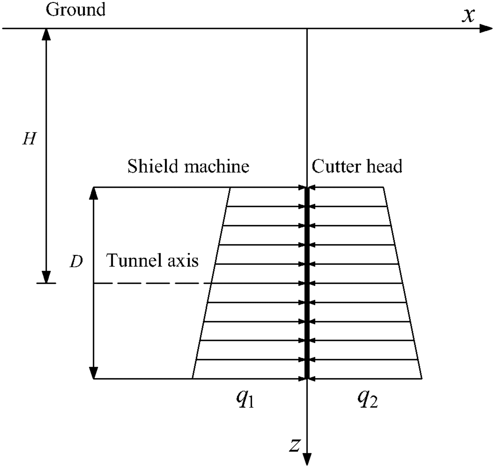
In shield tunneling, there must be a pressure difference between the support pressure applied to the excavation face and the earth and water pressure of the stratum, that is, the shield frontal additional thrust. At present, when many studies analyze the influence of the frontal thrust of shield machine, for earth pressure balance (EPB) shield and slurry shield, the pressure value at the center of the cutter at the excavation face is generally selected for the study, and it is assumed that the cutter frontal thrust and slurry pressure are uniformly distributed on the excavation face, or the additional frontal thrust is simply assumed to be 20 kPa (Deng et al. 2022 ; Jia and Gao 2022; Mei et al. 2022). However, when the diameter of the shield machine is small, it can be assumed that the cutter frontal thrust and slurry pressure are uniformly distributed on the excavation surface, but as the diameter of shield increases, the pressure difference of lateral ground pressure formed at the top and bottom of the excavation face cannot be ignored (Chen et al. 2019; Cheng et al. 2021a). To ensure the stability of the excavation surface, the frontal thrust of the cutter head and the slurry pressure applied by the large-diameter shield machine are non-uniformly distributed under the influence of the differential pressure and the self-weight of the lateral earth pressure of the stratum, and the distribution of support force of shield excavation face is shown in Fig. 1.
Fig. 1.
Fig. 1. Additional thrust on shield excavation face.
To ensure the stability of the excavation surface, the frontal thrust and slurry pressure are generally greater than the lateral pressure of the formation. Therefore, the additional thrust that takes into account the uneven distribution of formation lateral pressure effects is as follows:
q=q1q2
(1)
q2=K0γ(zH)
(2)
where q is the additional thrust generated by the cutter head of the shield machine; q1 is the frontal thrust of the cutter and mud pressure; q2 is the lateral earth and water pressure; K0 is the lateral pressure coefficient of the soil layer; γ is the soil layer weight; and H is the buried depth of the tunnel.
When there are no actual monitoring data, the additional thrust value can be obtained by the following methods according to Wang et al (Jiang et al. 2018; Wang 2009), when the EPB shield is used,
q=10.13(1μ)Euπv(1ξ)2(1+μ)(34μ)Dkuw+Δq
(3)
When the slurry shield is used,
q=q1q2kslγsl(zH)
(4)
where Δq′ is the squeezing pressure generated by the incision cut into the soil, generally taken as 10∼25kP; μ is the Poisson’s ratio of the soil; Eu is the undrained elastic modulus (kPa) of the soil; v is the shield tunneling speed (cm/min); w is the rotational speed of the cutter; ku is the amplitude of the closed part of the cutter; D is the diameter of the cutter (m); ξ is the opening rate of the cutter (%); γsl is the weight of slurry; and ksl is the lateral pressure coefficient of slurry.

2.3. Friction distribution considering soil softening and slurry spreading

In the process of shield tunneling construction, the friction between the shield shell and the surrounding soil will cause the horizontal displacement of the soil. In most of the current researches, it is generally assumed that the friction force is uniformly distributed on the shield casing, which is inconsistent with the actual situation. Liang et al. (2015) pointed out that the friction between the shield machine and the surrounding soil is similar to the friction characteristics of the pile–soil interface, and the surrounding soil softens during shield tunneling, and the friction is residual friction. According to the shear force formula at the pile–soil interface given by Alonso et al. (2009), the friction force f at any position on the shield shell can be obtained.
{f=βsσθtanδfσθ=σvsin2θ+σhcos2θσv=γHγRsinθσh=K0σv
(5)
In the formula, βs is the ratio of residual frictional resistance to ultimate frictional resistance; σθ is the radial normal stress received at any point of the shield machine casing; δf is the interface friction angle between the casing and the soil; and σv and σh are the pressure in vertical and horizontal directions.
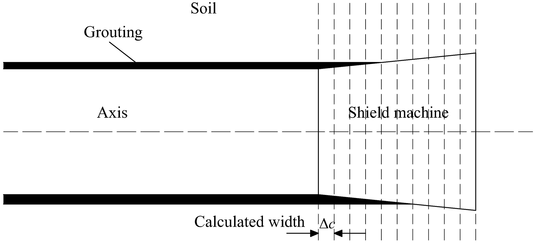
In previous research, it is usually assumed that the shield machine is a cylinder with a constant diameter. However, in fact, the diameter of the cutter head of the shield machine is larger than the diameter of the shield tail. This difference is very small, generally about 0.4% of the diameter of the shield machine. During the construction of the shield machine, there is a joint gap s between the tail of the shield machine and the soil due to the difference in the diameter of the front and rear of the shield machine, as shown in Fig. 2. Bezuijen (2009) and Nagel and Meschke (2011) found that the grouting slurry will spread to the joint gap of the shield tail during shield construction, and the friction force of the shield tail will be less affected by the slurry. In the calculation, the friction force at the shield tail needs to be multiplied by the reduction factor λ. The grouting spread distance a at any position of the shield tail can be obtained by changing the grouting pressure decay formula of the shield tail.
Δσ=2ΔRRG
(6)
ΔP=2Δasτp
(7)
Fig. 2.
Fig. 2. Slurry spread distance (not drawn to scale).
In the formula, Δσ is the change of grouting pressure; R′ is the radius of the shield machine and the thickness of the slurry; ΔR′ is the change of the radius; G is the shear modulus of the soil; ΔP is the change of the grouting pressure after the slurry flows; Δa is the length increment along the tunneling direction; and τ0 is the shear stress of shield tail grouting.
The calculation method is: divide the soil around the tunnel into independent areas of width Δa and use eq. (6) to calculate the joint width at the tail of the shield machine. This seam width can be used in eq. (7) to calculate the pressure change when grouting flows to the front of the shield machine at distance Δa. The resulting grouting pressure (original grouting pressure minus pressure change) is used to calculate changes in the next area and joint width, etc. For each calculation, it is checked whether the calculated seam width is still positive. When the joint width is 0, the soil is in contact with the shield machine, and the actual diameter of the shield machine in this area is used. For the specific calculation method of the grouting pressure at any position θ of the shield tail, see Section 2.4.

2.4. Grouting pressure distribution considering grouting diffusion

The grouting pressure of the shield tail has an important influence on the horizontal displacement of the soil. Most of the current studies have not considered the spatial non-uniform distribution of the grouting pressure. The synchronous grouting of shield tail is divided into two independent processes: formation and dissipation. The formation of grouting pressure occurs in the stage where the shield tail and the segment are pulled out. At this stage, the grouting hole releases the slurry, and in a very short time the slurry flows along the gap between the shield tail and the segment is filled in the circumferential direction. Due to the influence of the grouting pressure distribution in the grouting hole, the slurry density, and the slurry diffusion, the circumferential grouting pressure distribution is usually a non-uniform distribution pattern with small upper and big lower. The process of grouting pressure dissipation occurs within a certain range behind the shield tail. At this time, the new grouting liquid in the circumferential direction squeezes the grouted liquid, and the extrusion effect gradually decays with the increase of the distance from the shield tail until the grouting pressure reaches a balance with the water and soil pressure of the surrounding stratum. Therefore, the grouting pressure is generated at the shield tail and decays within a certain range behind the shield tail. This is quite different from the simplified treatment of grouting pressure in most existing studies. According to the analysis of the circumferential and longitudinal filling diffusion mechanism of the slurry during the simultaneous grouting process of the shield tail, the following basic assumptions are put forward to construct the theoretical model of its circumferential and longitudinal filling diffusion:
① The slurry is an incompressible and isotropic homogeneous fluid, ignoring the loss and property change of the slurry during the diffusion process;
② After the slurry flows out of the grouting pipe, it first fills the gap in the circumferential direction and then flows in the axial direction of the tunnel in the gap of the shield tail;
③ The axial pressure of the slurry at the same point is equal to the radial pressure;
④ Since the hoop filling stage usually takes only tens of seconds to complete, therefore, regardless of the time spent in the hoop filling stage, the moment when the slurry filling is completed along the hoop is set as the start time of grouting.
1.
Circumferential distribution of grouting pressure
According to the characteristics of the grouting slurry and referring to the existing research, this paper assumes that the grouting slurry is Bingham fluid and analyzes it. The annular distribution formula of the grouting pressure P in the shield tail is
P=Pi+ρpgRg(cosαicosα)±Y(αiα)
(8)
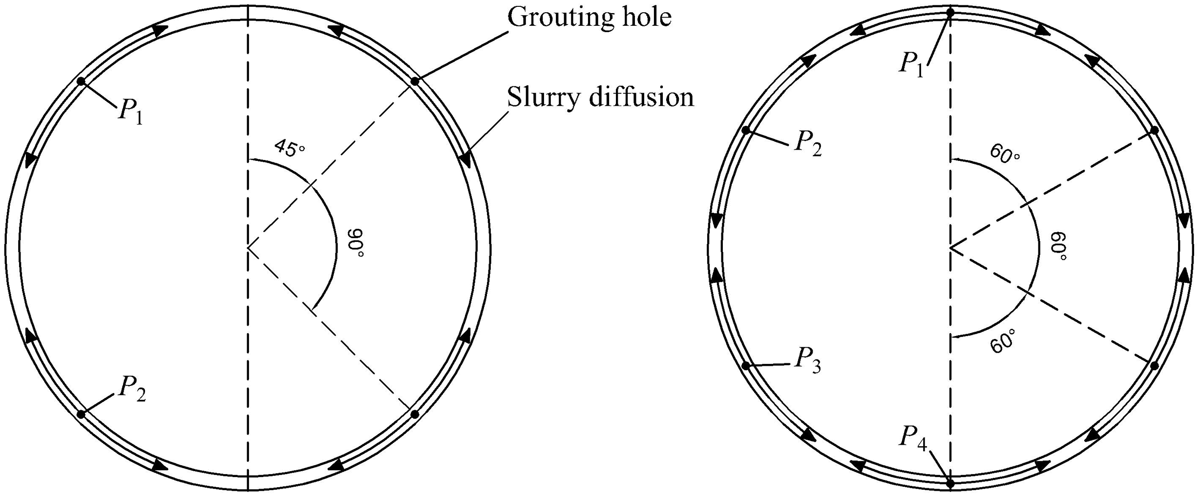
where i is the number of the grouting hole; Pi is the grouting pressure at the number; “±” is “+” when the slurry spreads downward, and “–” otherwise; ρp is the density of the slurry; g is the acceleration of gravity; Rg is the outer diameter of the pipe; G is the angle between the grouting hole at the number and the vertical direction; and αi is the slurry diffusion angle, when the slurry spreads upward, max α = (αi + αi–1)/2 and when the slurry spreads downward, max α = (αi + αi+1)/2.
Y3(3Rgτ0δp+12Rgμpqpbδp3)Y24Rg3τ03δp3=0
(9)
In the formula, τ0 is the static shear force of the grouting slurry; μp is the plastic viscosity coefficient of the slurry; b is the gap size of the shield tail; δp is the thickness of the slurry flow pancake, δp = v t; v is the shield tunneling speed; t is the time required for the slurry to fill the gap when the shield tail is synchronously grouted, generally 30∼100 s; and qp is the interface flow, qpπRgbvm/n.
At present, 4 or 6 grouting holes are generally set for synchronous grouting of shield machine, and the applied grouting pressure is left and right symmetrical. The circumferential distribution of grouting pressure with different numbers of grouting holes is shown in Fig. 3.
Fig. 3.
Fig. 3. Circumferential distribution of grouting pressure.
2.
Longitudinal distribution of grouting pressure
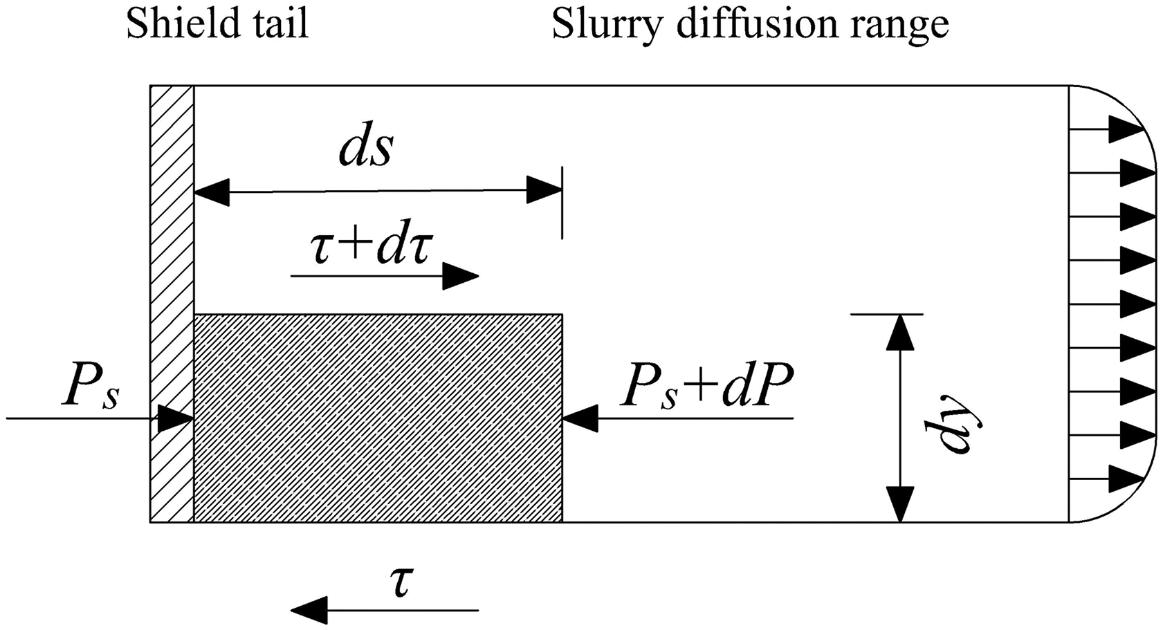
The longitudinal diffusion model of grouting slurry is shown in Fig. 4. Taking the longitudinal slurry-micro-element as the research object, and analyzing the force of the micro-element, the force balance equation can be obtained:
Psdy(Ps+dP)dyτds+(τ+dτ)ds=0
(10)
Fig. 4.
Fig. 4. Longitudinal diffusion model of grouting pressure.
Let dPs/ds = B, according to the boundary conditions, at the tail of the shield, S = 0, Ps = P, then the pressure distribution equation of the slurry along the longitudinal direction of the tunnel is
Ps=PBS
(11)
In the formula, Ps is the longitudinal grouting pressure at the distance S from the shield tail, and it will not attenuate when the grouting pressure attenuates to equilibrium with the formation pressure; S is the distance from the shield tail, 0 < S < l; l is the grouting slurry diffusion length; B is the attenuation strength of the grouting pressure along the longitudinal direction; and τ is the shear force of the slurry.
B can be solved by Bingham’s fluid continuity equation, and the exact expression after the solution is
B=4τ03(12μpqpb+3τ0h2h3)3312πRg2μpvmδp3n
(12)
In the formula, h is the filling width of the slurry; m is the injection rate of the slurry, generally 1.1∼1.8; and n is the number of grouting holes.
3.
Spatial distribution of grouting pressure
Combining eq. (1) and eq. (3), the formula for calculating the spatial distribution of grouting pressure can be obtained:
Ps=Pi+ρpgRg(cosαicosα)±Y(αiα)BS
(13)

3. Calculation of horizontal displacement caused by shield construction

3.1. Mindlin basic solution

Mindlin (1936) deduced the calculation formulas of the vertical displacement and the horizontal displacement of any point (x′, y′, z′) in the space when a point (0, 0, c) in a semi-infinite elastic space is affected by the vertical concentration force Pv and the horizontal concentration force Ph. Under the action of the vertical concentration force Pv and the horizontal concentration force Ph, the horizontal displacements vv and vh of any point in the soil are shown in eqs. (14) and (15).
vv=Pvx2+y2cosϕ16πG(1μ)[zcR13+(34μ)(zc)R234(1μ)(12μ)R2(R2+z+c)+6cz(z+c)2R25]
(14)
vh=Ph16πG(1μ){34μR1+1R2+y2R13+(34μ)y2R23+2zcR23(13y2R22)+4(1μ)(12μ)(R2+z+c)[1y2R2(R2+z+c)]}
(15)
where G is the shear modulus of the soil (kPa), and μ is the Poisson’s ratio.
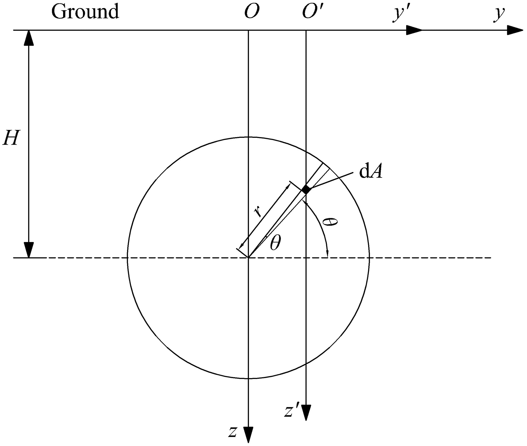
{R1=x2+y2+(zc)2R2=x2+y2+(z+c)2c=Hrsinθ
(16)
Set the space coordinate xyz, and the local coordinate x′y′z′, the corresponding coordinate axes of the two coordinate systems are parallel to each other, and the offset distances of the local coordinate system are l, m, and n, respectively.
{x=xly=ymz=zn
(17)
Substituting eq. (17) into eqs. (14)(16) can obtain the vertical displacement and horizontal displacement at any point (x, y, z) in the spatial coordinates of the soil.

3.2. Horizontal displacement caused by uneven distribution of additional thrust on the excavation face

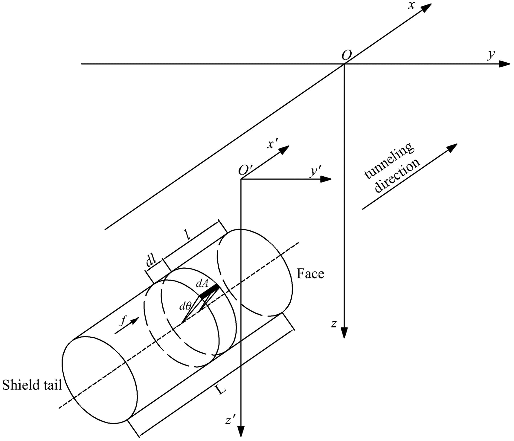
When the shield machine is excavating, the calculation model of soil deformation caused by the additional thrust of the excavation surface is shown in Fig. 5. The area of any element in the excavation surface is dA = rdrdθ, where r is the distance from the element to the center of the excavation surface and θ is the angle between the element and the horizontal plane of the center of the excavation surface, l = 0, m = rcosθ, n = 0.
Fig. 5.
Fig. 5. Calculation model of additional thrust on excavation face.
Calculation formula of horizontal displacement caused by uneven distribution of additional thrust on excavation face during shield tunneling construction is as follows:
vh=0R02πqrxy16πG(1μ)[1R13+34μR234(1μ)(12μ)R2(R2+z+c)26czR25]drdθ
(18)

3.3. Horizontal displacement caused by uneven distribution of shield friction

The calculation model of the formation deformation caused by the friction force f between the shield machine shell and the surrounding soil is shown in Fig. 6. Let the length of the shield from the excavation cutter head to the shield tail be L, and the area of any element on the surface of the shell is dA = Rdθdl, where l is the axial distance from the element to the excavation surface, and the concentrated force is dPh = f Rdθdl.
Fig. 6.
Fig. 6. Calculation model of shield friction force.
The horizontal displacement caused by the frictional force of the shield shell during the shield tunneling construction can be calculated by the integral of eq. (14).
dvf=0L02πfRxy16πG(1μ)[1R13+34μR234(1μ)(12μ)R2(R2+z+c)26czR25]dldθ
(19)
From the analysis in Section 2.2, it can be seen that due to the influence of the shield tail slurry spreading, the friction force needs to be calculated in different regions.
vf=0Lc02πdvf1+LcL02πdvf2
(20)

3.4. Horizontal displacement caused by uneven distribution of grouting pressure in shield tail

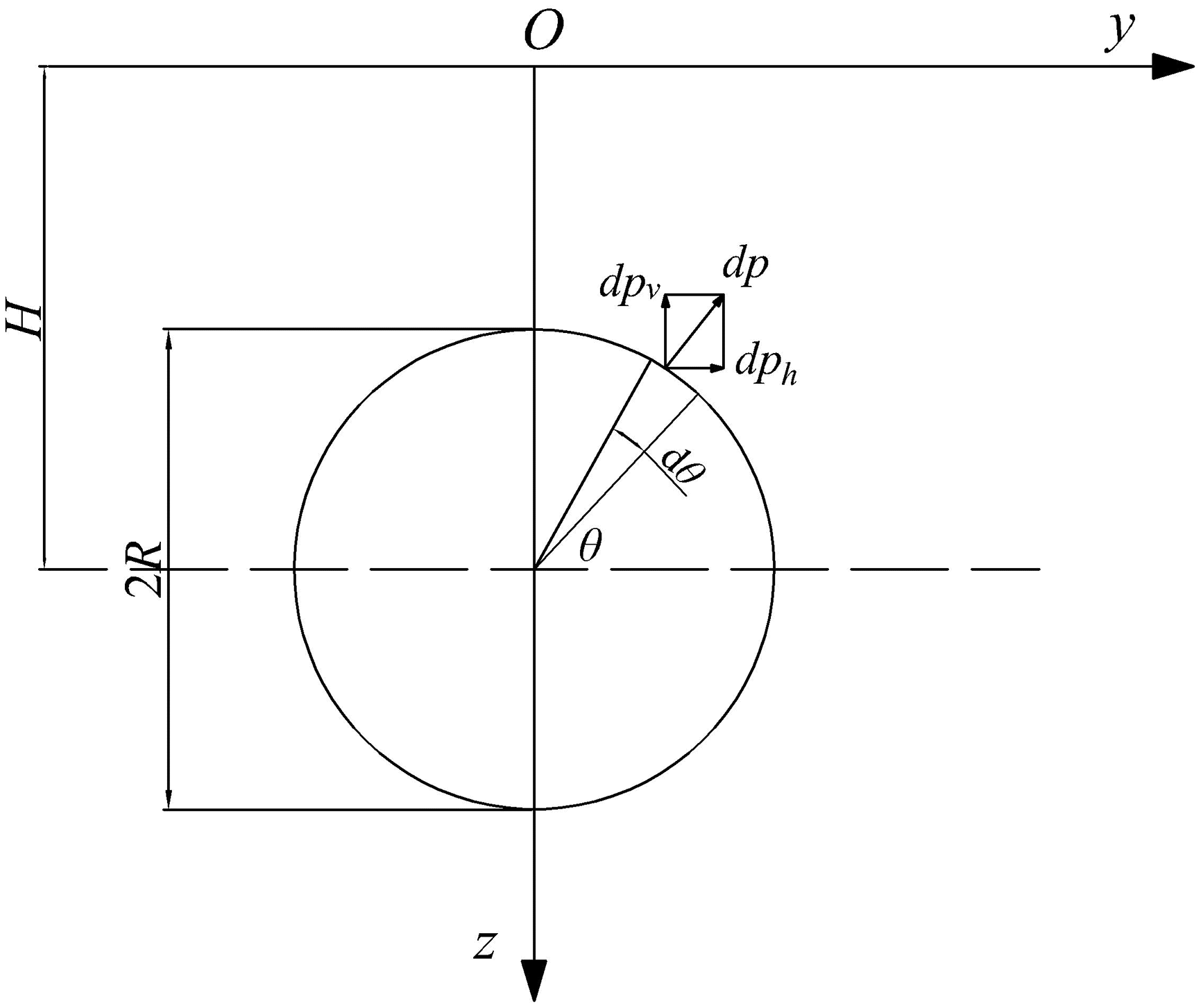
As shown in Fig. 7, the length of the shield from the shield tail to the grouting end is S, the grouting pressure at the shield tail is p, the grouting pressure decays along the grouting length, and the grouting pressure at the distance S away from the shield tail will decrease to 0, any element dA = Rdθds, and its concentrated force dp can be decomposed into horizontal component force dph and vertical component force dpv. Because the influence of vertical component force is small and can be ignored, this paper only considers formation deformation caused by horizontal component force.
Fig. 7.
Fig. 7. Calculation model of shield tail grouting pressure.
Set l = −L−s, m = Rcosθ, n = 0, and substitute them into eq. (15) to transform the coordinate system. The horizontal displacement caused by grouting pressure in shield tunneling construction can be calculated by the integral calculation of eq. (15).
vp=0S02π(Pcosθ)R16πG(1μ){34μR1+(yRcosθ)2R13+1R2+(34μ)(yRcosθ)2R23+2z(HRsinθ)R23[13(yRcosθ)2R22]+4(1μ)(12μ)(R2+z+c)[1(yRcosθ)2R2(R2+z+c)]}dsdθ
(21)

3.5. Horizontal displacement caused by formation loss

Horizontal displacement formula of the soil above caused by tunnel construction is as follows:
vs=VlR2y{1y2+(Hz)2+34μy2+(H+z)24z(H+z)[y2+(H+z)2]2}exp{[1.38y2(H+R)2+0.69z2H2]}
(22)
where Vl is the formation loss rate. A three-dimensional calculation formula for the formation loss along the direction of tunnel excavation is as follows:
Vl(x)=Vl2(1xx2+y2+H2)
(23)
Since the stratum loss at the excavation face is basically less than half of the maximum stratum loss at the rear, based on this consideration, a formula for the horizontal displacement of soil mass caused by soil mass loss under three-dimensional conditions is given.
vs=VlR2y2(1xx2+y2+H2){1y2+(Hz)2+34μy2+(H+z)24z(H+z)[y2+(H+z)2]2}exp{[1.38y2(H+R)2+0.69z2H2]}
(24)

3.6. Total displacement of stratum caused by shield advancement

The above displacement formulas are superimposed to obtain the solution of the horizontal displacement of the soil caused by the advancement of the shield.
v=vq+vf+vp+vs
(25)

4. Engineering case analysis

To verify the validity of the proposed calculation method, this paper selects two engineering cases and compares the calculation results of different calculation methods to study the influence of uneven distribution of disturbance force on the horizontal displacement of soil caused by shield construction under the influence of multiple factors. Positive values indicate that the soil moves in the direction away from the tunnel, otherwise vice versa.

4.1. Engineering Case 1

Taking a shield tunnel project of Shanghai Metro Line 2 as an example, the stratum in this area has the characteristics of sensitivity, saturation, and low permeability, and the EPB shield machine is used for construction. This section passes through the prosperous commercial area of Shanghai and has strict requirements on stratum deformation, and shield tunneling is relatively cautious. For the specific soil profile and parameters, please refer to the literature Lee et al. (1999) and Liang et al. (2015). The required calculation parameters are as follows: H = 15 m; γ = 17.8 KN/m3; K0 = 0.57; G = 3.5 MPa; μ = 0.35; v = 12 m/d; L = 6.24 m; R = 3.17 m; Rg = 3.15 m; S = 1 m; n = 4; q = 58.9 kPa; βs = 0.85; δf = 22°; λ = 0.85; p1 = p4 = 400 kPa; p2 = p3 = 100 kPa; ρp = 2190 kg/m3; μp = 1.8 Pa·s; m = 1.2; τ0 = 1.8 × 10−2 kPa; t = 100 s; and Vs = 0.14%.
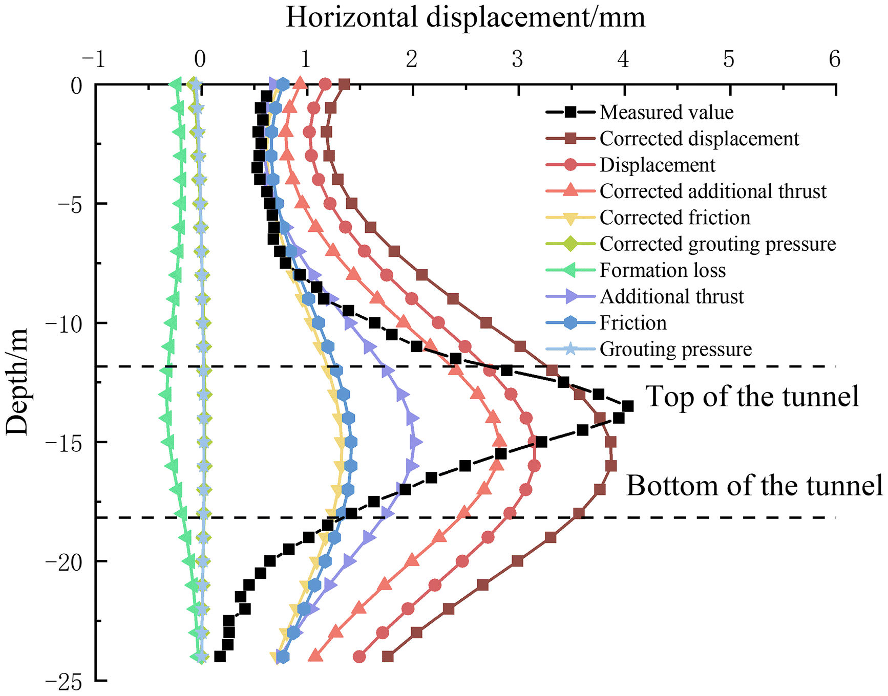
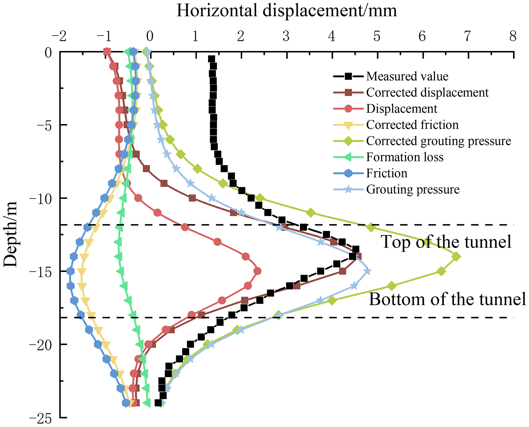
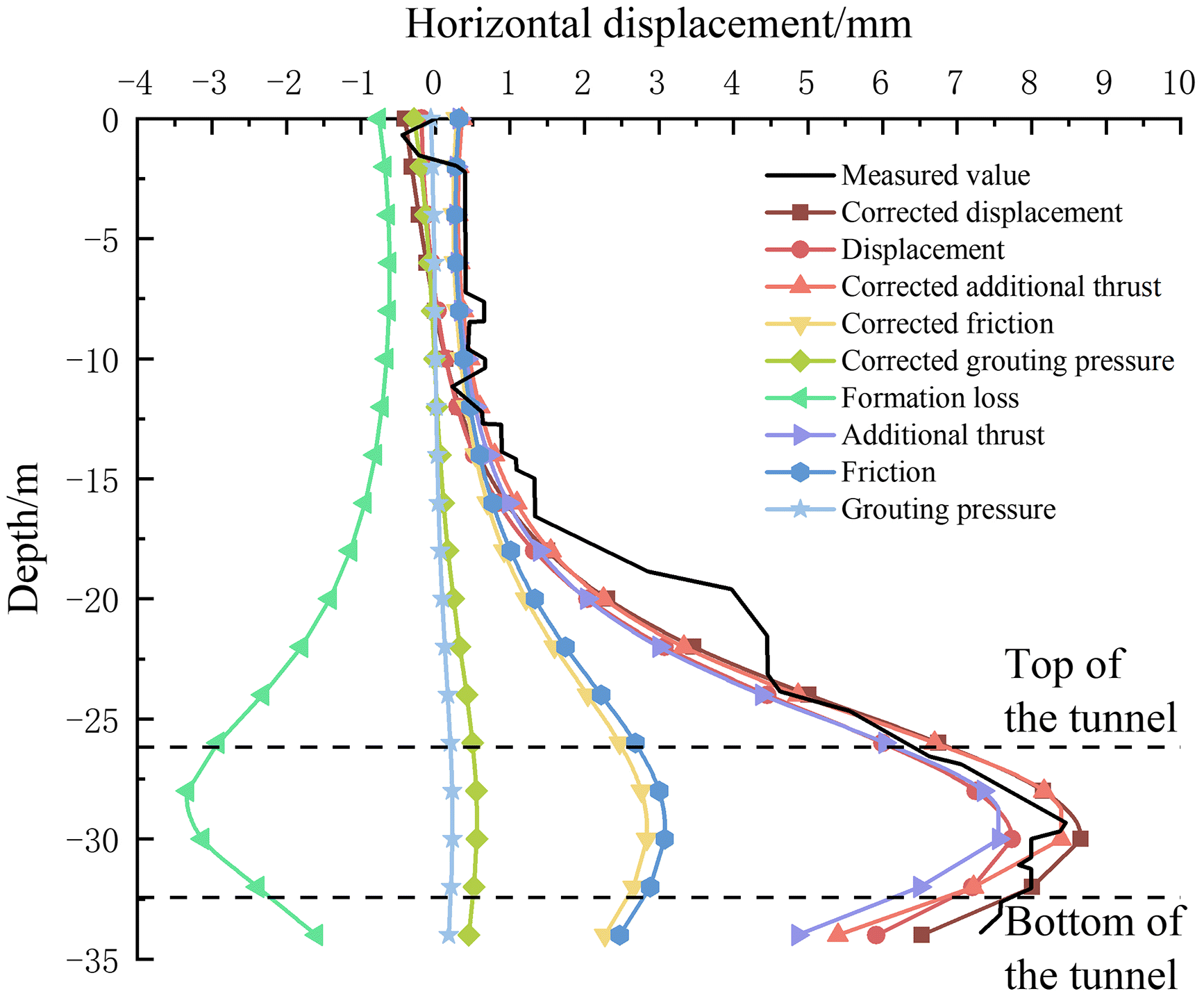
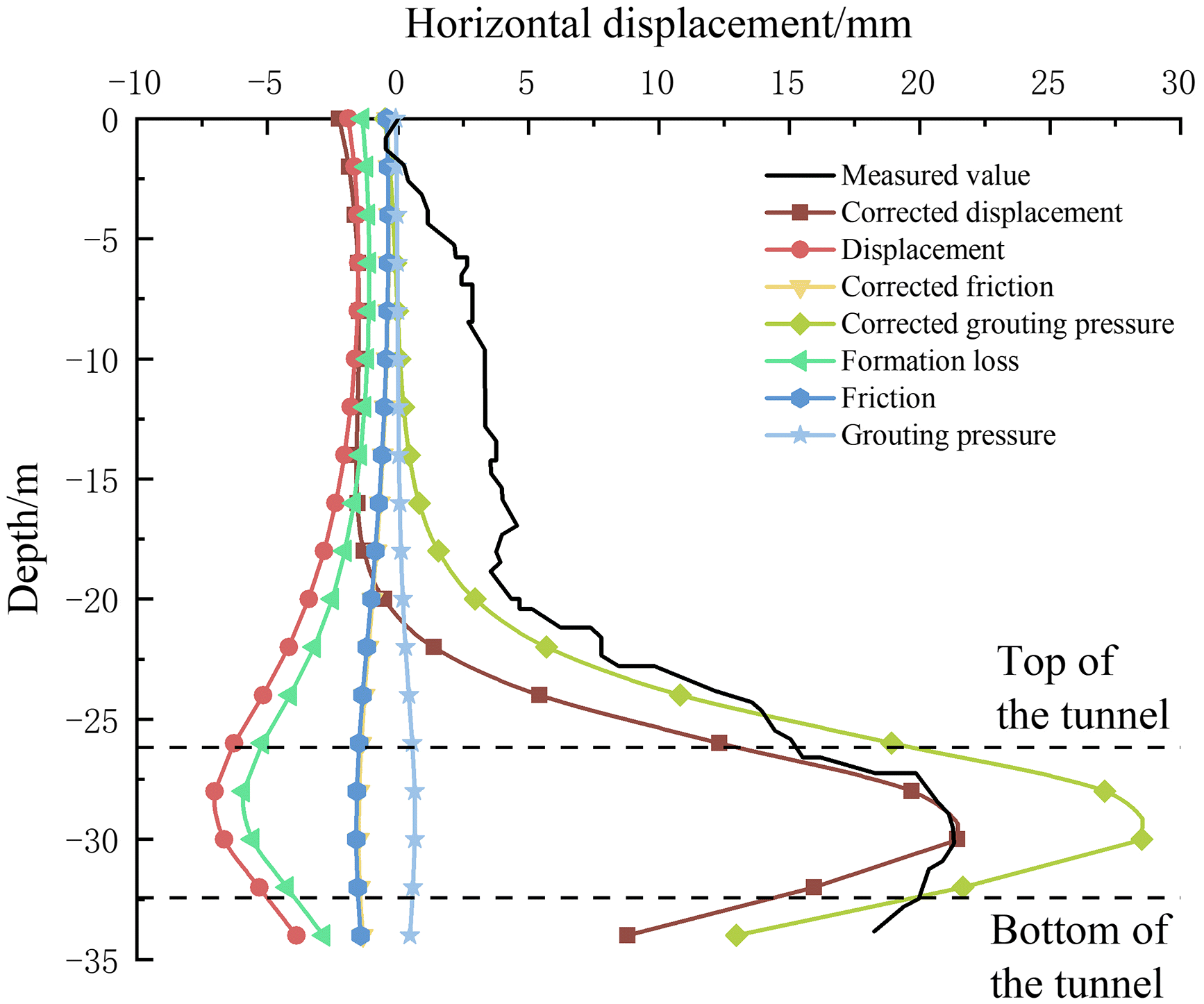
Two cross-section positions 1D in front and 1D behind the excavation of the shield machine are selected for research. The horizontal distance from the monitoring point to the tunnel axis is 6.2 m. The horizontal deformation of the formation is calculated for both sections. Compare the calculated value with the field measured value and the calculation result of the prediction formula in the literature, as shown in Figs. 89. The horizontal deformation of the soil behind the excavation face is not affected by the additional thrust, and the horizontal displacement value is positive when it is away from the tunnel side.
1.
Affected by the disturbance force of shield construction, the horizontal displacement direction of the deep soil body is the direction away from the shield tunnel, and the horizontal displacement behind the excavation face is greater than that in front of the excavation face, and the peak value of the horizontal displacement appears near the tunnel axis.
2.
It can be found from Fig. 8 that when calculating the horizontal displacement in front of the excavation face, the calculated results considering the non-uniform distribution of disturbance forces agree well with the measured values, and the error between the calculated results assuming uniform distribution of disturbance forces and the measured values is large, but within acceptable limits. The horizontal displacement of the modified prediction formula converges faster on both sides of the tunnel axis.
3.
It can be seen from Fig. 9 that when calculating the horizontal displacement behind the excavation face, the existing prediction formula assumes that the disturbance force is uniformly distributed, and the calculation result has a large error. The final calculation result is only about half of the measured value, and the peak value of the horizontal displacement appears at the tunnel axis, while the peak value of the measured value is above the axis, which is different from the measured result. The correction formula takes into account the uneven distribution of different disturbance forces under the influence of multiple factors. The final calculated results are in better agreement with the measured deformation values, and the error is smaller. When the distance is far from the tunnel axis, the error between the calculation curve of the existing prediction formula and the modified prediction formula and the measured value is large, which may be the influence of the diffusion of the tunnel grouting slurry in the soil. When the mechanical properties of the upper and lower soil layers are quite different, the horizontal displacement of the soil mass will also be affected.
4.
It can be found from Figs. 89 that the effect of the modified additional thrust on the horizontal displacement of the soil is greater. Considering the influence of grouting spread, the final calculation result of friction force is smaller and more realistic. The spatiotemporal uneven distribution of grouting pressure has little effect on the horizontal displacement of the soil in front of the shield, which is basically the same as the calculation result of the existing formula, and has a great influence on the soil deformation behind the excavation face. When the space-time is not uniformly distributed, it will cause large error to the final result.
Fig. 8.
Fig. 8. Influence of different disturbance forces at 1D in front of the excavation face.
Fig. 9.
Fig. 9. Influence of different disturbance forces at 1D behind the excavation face.

4.2. Engineering Case 2

Taking the Luoxi–Nanzhou section of Guangzhou Rail Transit Line No. 2 and No. 8 as an example, the tunnel is constructed with two earth pressure shield machines. The landform of the project site belongs to the alluvial plain of the Pearl River Delta, and the ground is flat. For details of soil profile and parameters, please refer to Jiang et al. (2011). The required calculation parameters are as follows: H = 29.3 m; γ = 16.14 KN/m3; K0 = 0.53; G = 1.8 MPa; E = 4.71 MPa; μ = 0.28; v = 18 m/d; L = 7.5 m; R = 3.13 m; Rg = 3.05 m; S = 1.5 m; n = 4; q = 50 kPa; p1 = p2 = p3 = p4 = 350 kPa; δf = 4.5°; βs = 0.9; λ = 0.85; ρp = 2150 kg/m3; μp = 1.7 Pa·s; m = 1.2; τ0 = 1.8 × 10−2 kPa; t = 100 s; and Vs = 0.99%.
Two cross-section positions 4.5 m in front and 18 m behind the excavation face of the shield machine are selected for research. The horizontal distance from the monitoring point to the tunnel axis is 6 m. Use the revised prediction formula and the existing prediction formula to calculate the horizontal displacement of the stratum of the two sections, and compare the calculation results with the field measured values, as shown in Figs. 1011.
1.
The horizontal displacement law of soil caused by shield construction is consistent with Case 1. When calculating the horizontal displacement in front of the excavation, the calculation results considering the non-uniform distribution of the disturbance force are in better agreement with the measured values, which can reflect the change trend of the measured horizontal displacement.
2.
It can be seen from Fig. 11 that when calculating the horizontal displacement behind the excavation face, the calculation results of the existing prediction formula have great error. The calculation results show that the soil moves to the side of the tunnel, which is completely opposite to the measured value. In the calculation of the modified prediction formula, the uneven distribution of different disturbance forces under the influence of multiple factors is considered, and the final calculation result is in better agreement with the measured deformation value, and the error is smaller.
Fig. 10.
Fig. 10. Influence of different disturbance forces at 4.5 m in front of the excavation front.
Fig. 11.
Fig. 11. Influence of different disturbance forces at 18 m behind the excavation face.

5. Conclusion

Based on the Mindlin solution theory, this paper considers the influence of the non-uniform distribution of disturbance force on the horizontal displacement of soil and modifies the existing prediction formula. It is verified by engineering cases, which proves the validity and reliability of the calculation method in this paper. The main conclusions are as follows:
1.
Affected by the disturbance force of shield construction, the horizontal displacement direction of the deep soil body is away from the direction of the shield tunnel, and the horizontal displacement behind the excavation face is greater than that in front of the excavation face, and the peak value of the horizontal displacement occurs near the tunnel axis or obliquely above.
2.
After the verification of engineering cases, when calculating the horizontal displacement in front of the excavation face, the calculation results of the revised formula and the original formula are in good agreement with the measured values, which can reflect the change trend of the horizontal displacement of the soil, and the calculation results of the modified formula are more accurate. When calculating the horizontal displacement behind the excavation face, the existing formula assumes that the disturbance force is uniformly distributed, and the error of the calculation result is very large, which is different from the law of the measured result. The calculation result of the revised prediction formula is in better agreement with the measured deformation value, the error is smaller, and it is more in line with the actual engineering.
3.
The uneven distribution of the additional thrust has little effect on the horizontal displacement of the soil. The spatial and temporal uneven distribution of grouting pressure has little influence on the horizontal displacement of the soil in front of the shield but has a great influence on the deformation of the soil behind the excavation face.

Acknowledgements

This work was financially supported by the Natural Science Foundation of China (51774173) and the Liaoning Province “rejuvenating Liaoning talents plan” project (XLYC207163).

References

Alonso E, Josa A, and Villalba A. 2009. Negative skin friction on piles: A simplified analysis and prediction procedure. Géotechnique, 34(3): 341–357.
Bezuijen A. 2009. The influence of grout and bentonite slurry on the process of TBM tunnelling. Der Einfluss von Ringspaltmörtel und Bentonitsuspension auf den TBM-Vortrieb. Geomechanics and Tunnelling, 2: 294–303.
Burd H, Yiu WN, Acikgoz S, and Martin C. 2022. Soil-foundation interaction model for the assessment of tunnelling-induced damage to masonry buildings. Tunnelling and Underground Space Technology, 119: 104208.
Cao L, Zhang D, and Fang Q. 2020. Semi-analytical prediction for tunnelling-induced ground movements in multi-layered clayey soils. Tunnelling and Underground Space Technology, 102: 103446.
Chen RP, Lin XT, and Wu HN. 2019. An analytical model to predict the limit support pressure on a deep shield tunnel face. Computers and Geotechnics, 115.
Cheng C, Chen Y, Zhao C, Zhao W, Han J, and Li T. 2022. Theoretical analysis of the shield tunnel face stability in dry sandy strata. European Journal of Environmental and Civil Engineering.
Cheng C, Jia P, Zhao W, Ni P, Bai Q, Wang Z, and Lu B. 2021a. Experimental and analytical study of shield tunnel face in dense sand strata considering different longitudinal inclination. Tunnelling and Underground Space Technology, 113: 103950.
Cheng C, Ni P, Zhao W, Jia P, Gao S, Wang Z, and Deng C. 2021b. Face stability analysis of EPB shield tunnel in dense sand stratum considering the evolution of failure pattern. Computers and Geotechnics, 130: 103890.
Chou WI, and Bobet A. 2002. Prediction of ground deformations in shallow tunnels in clay. Tunnelling and Underground Space Technology, 17: 3–19.
Deng HS, Fu HL, Yue S, Zhen H, and Zhao YY. 2022. Ground loss model for analyzing shield tunneling-induced surface settlement along curve sections. Tunnelling and Underground Space Technology, 119: 104250.
Jia BX, and Gao ZX. 2022. Investigating Surface Deformation Caused by Excavation of Curved Shield in Upper Soft and Lower Hard Soil. Frontiers in Earth Science, 10: 844969.
Jiang XL, Cui Y, Li Y, and Zhao Z. 2005. Measured and dynamic simulation of stratum deformation during shield construction of Tianjin subway. Geotechnical Mechanics, 10: 91–95.
Jiang XL, Li L, Yuan J, and Yin J. 2011. Dynamic analysis of horizontal displacement of stratum in deep subway shield construction. Rock and Soil Mechanics, 32(4): 1186–1192.
Jiang X, Zhang X, Chen A, Chen J, and Bai Y. 2018. Ground Surface Deformation Analysis of Quasi Rectangular EPB Shield Tunneling. Proceedings of GeoShanghai 2018 International Conference: Tunnelling and Underground Construction. pp. 103–111.
Jin H, Yuan D, Dalong J, Wu J, Wang X, Han B, and Mao J. 2022. Shield kinematics and its influence on ground settlement in ultra-soft soil: A case study in Suzhou. Canadian Geotechnical Journal, 59.
Klar A. 2022. A Fourier-based elastic continuum solution for jointed pipeline response to tunneling. Tunnelling and Underground Space Technology, 119: 104237.
Lee KM, Ji HW, Shen CK, Liu JH, and Bai TH. 1999. Ground Response to the Construction of Shanghai Metro Tunnel-Line 2. Soils and Foundations, 39: 113–134.
Liang RZ, Xia TD, Lin CG, and Yu F. 2015. Analysis of surface deformation and horizontal displacement of deep soil caused by shield advancement. Chinese Journal of Rock Mechanics and Engineering, 34(3): 583–593.
Loganathan N, and Poulos H. 1998. Analytical prediction for tunneling-induced ground movements in clays. Journal of Geotechnical and Geoenvironmental, 124.
Mei Y, Zhou D, Shi W, Zhang Y, and Zhang Y. 2022. Laws and numerical analysis of surface deformation caused by excavation of large diameter slurry shield in upper-soft and lower-hard composite stratum. Buildings, 12: 1470.
Mindlin R. 1936. Force at a Point in the Interior of a Semi-Infinite Solid. Physics, 7: 195–202.
Nagel F, and Meschke G. 2011. Grout and bentonite flow around a TBM: Computational modeling and simulation-based assessment of influence on surface settlements. Tunnelling and Underground Space Technology, 26: 445–452.
Qi Y, Wei G, Feng F, and Zhu J. 2020. Method of calculating the compensation for rectifying the horizontal displacement of existing tunnels by grouting. Applied Sciences, 11: 40.
Sheng M, Gao J, Guo P, Cao RH, and Wang Y. 2021. Temporal-spatial characteristics of ground and pile responses to twin shield tunneling in clays. Geofluids, 2021: 1–15.
Standing JR, and Selemetas D. 2013. Greenfield ground response to EPBM tunnelling in London Clay. Géotechnique, 63: 989–1007.
Tian XY, Gu SC, and Huang RB. 2017. Simplified analysis about horizontal displacement of deep soil under tunnel excavation. IOP Conference Series: Earth and Environmental Science. 94: 012002.
Wang HX. 2009. Effect of cutter head com pressing the front soil and influence of head aperture ratio on contact pressure of EPB shield to the front soil. China Civil Engineering Journal. 42: 113–118.
Wu L, Zhang Z, Zhang X, and Lin F. 2018. The Vertical and Horizontal Displacements of Cross-River Twin-Tunnels Surroundings Induced by Tunneling. IABSE Conference, Kuala Lumpur 2018: Engineering the Developing World.
Ye XW, Tao J, and Chen YM. 2022. Machine learning-based forecasting of soil settlement induced by shield tunneling construction. Tunnelling and Underground Space Technology, 124: 104452.
Zhu J, Zhu D, Yao H, and Huang F. 2021. The pore water pressure and soil displacement induced by underwater shield tunneling: A case study. Arabian Journal of Geosciences, 14: 1291.

Information & Authors

Information

Published In

cover image FACETS
FACETS
Volume 8Number 1January 2023
Pages: 1 - 17
Editor: Nicholas Vlachopoulos

History

Received: 6 September 2022
Accepted: 1 December 2022
Version of record online: 9 March 2023

Data Availability Statement

All data, models, and code generated or used during the study appear in the submitted article.

Key Words

  1. shield construction
  2. non-uniform distribution
  3. Mindlin solution
  4. horizontal displacement
  5. disturbance force

Sections

Subjects

Plain Language Summary

Predicting soil horizontal displacement by various disturbance factors during shield construction

Authors

Affiliations

Bao-xin Jia
School of Civil Engineering, Liaoning Technical University, Fuxin, Liaoning, China
Liaoning Key Laboratory of mine subsidence disaster prevention and control, Fuxin, Liaoning, China
Zong-xian Gao [email protected]
School of Civil Engineering, Liaoning Technical University, Fuxin, Liaoning, China
Hong-yan Hua
School of Civil Engineering, Liaoning Technical University, Fuxin, Liaoning, China

Author Contributions

HH performed the experiments/collected the data.
ZG conceived and designed the study.
ZG analyzed and interpreted the data.
BJ contributed resources.
BJ and ZG drafted or revised the manuscript.

Competing Interests

The authors declare no competing interests.

Metrics & Citations

Metrics

Other Metrics

Citations

Cite As

Export Citations

If you have the appropriate software installed, you can download article citation data to the citation manager of your choice. Simply select your manager software from the list below and click Download.

There are no citations for this item

View Options

View options

PDF

View PDF

Get Access

Media

Media

Other

Tables

Share Options

Share

Share the article link

Share on social media